SFM14-M View Datasheet(PDF) - Willas Electronic Corp.
Part Name
Description
Manufacturer
SFM14-M Datasheet PDF : 4 Pages
| |||
WILLAS
1.0A1S.0UAFSRUARFCAECME OMOUUNNTTSSUCPHEORTTFKAYSBTARRREICERTIRFEIECRTSIFI-E5R0S-6-2000VV- 200V
SOSDO-1D2-132-3L+PAPCACKKAAGGEE
FM120-M+
S F M 1 1T-HMRU
TFHMRU1200-M+
S F MP1b F8re-eMProduct
Features
• Batch process design, excellent power dissipation offers
Packinbegtteirnrefvoerrsme leaatkiaogencurrent and thermal resistance.
• Low profile surface mounted application in order to
optimize board space.
• Low power loss, high efficiency.
• High current capability, low forward voPl0tage drop.
• High surge capability.
P1
• Guardring for overvoltage protection.
d
• Ultra high-speed switching.
• Silicon epitaxial planar chip, metal silicon junction.
E
• Lead-free parts meet environmental standards of
MIL-STD-19500 /228
F • RoHS product for packing code suffix "G"
Halogen free product for packing code suffix "H"
W
B
Mechanical data
• Epoxy : UL94-V0 rated flame retardant
• Case : Molded plastic, SOD-123H
•
A
Terminals
:Plated
terminals,
solderable
P
per
,
MIL-STD-750
Method 2026
• Polarity : Indicated by cathode band
• Mounting Position : Any
• Weight : Approximated 0.011 gram
Package outline
SOD-123H
0.146(3.7)
0.130(3.3)
0.012(0.3) Typ.
0.071(1.8)
0.056(1.4)
0.031(0.8) Typ.
0.040(1.0)
0.024(0.6)
0.031(0.8) Typ.
Dimensions in inches and (millimeters)
MAXIMUM RATINGS AND ELECTRICAL CHARACTERISTICS
Ratings at 25℃ ambient temperature unless otherwise specified.
Single phase half wave, 60Hz, resistive of inductive load.
T
For capacitive load, derate current by 20%
D2
D1
RATINGS
Marking Code
Maximum Recurrent Peak Reverse Voltage
Maximum RMS Voltage
Maximum DC Blocking Voltage
Maximum Average Forward Rectified Current
SYMBOL FM120C-MH FM130-MH FM140-MH FM150-MH FM160-MH FM180-MH FM1100-MH FM1150-MH FM1200-MH U
12
13
14
15
16
VRRM
20
30
40
50D 60
18
10 W1 115
120
80
100
150
200 V
VRMS
14
21
28
35
42
56
70
105
140 V
VDC
20
30
40
50
60
80
100
150
200 V
IO
u1n.it0:mm
A
Peak Forward Surge Current 8.3 ms single half sine-wave IFSM
30
A
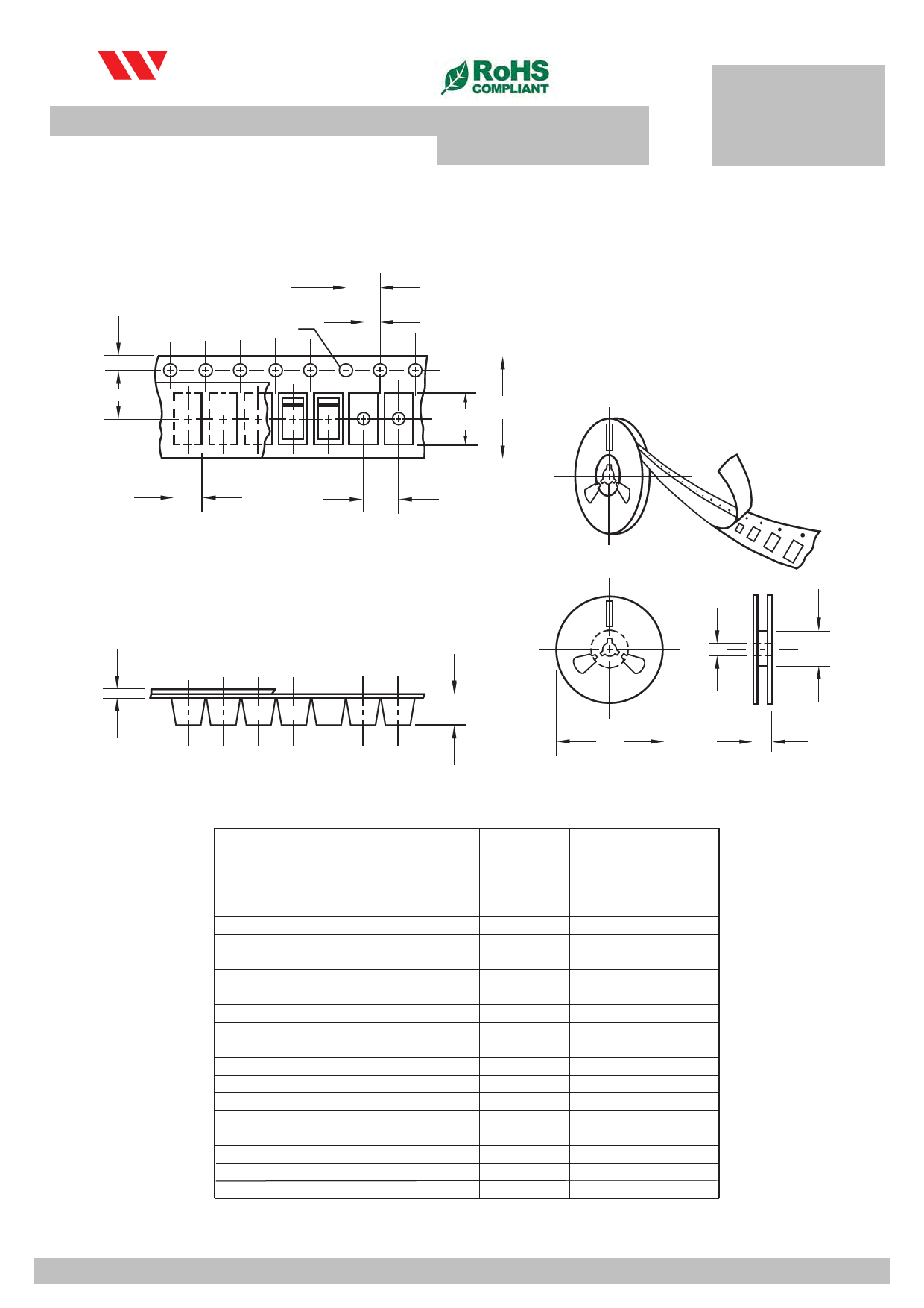
superimposed on rated load (JEDEC method) Item
Symbol Tolerance
SOD-123-L
Typical Thermal Resistance (Note 2)
RΘJA
40
℃
Typical Junction Capacitance (Note 1)
Carrier width
Operating Temperature Range
Carrier length
Storage Temperature Range
Carrier depth
CJ
TJ
TSTG
A -55 to +102.15
B
0.1
C
0.1
120
1.90
3.-9605 to +175
1.68
-55 to +150
Sprocket hole
d
0.1
1.50
CHARACTE1R3I"SRTIeCeSl outside diameStYeMr BOL FM12D0-MH FM130-MH2.F0M140-MH FM150-MH FM16-0-MH FM180-MH FM1100-MH FM1150-MH FM1200-MH U
Maximum Forward Voltage at 1.01A3"DRCeel inner diameter VF
D1
0m.5in0
0.70 -
0.85
0.9
0.92 V
Maximum Average Reverse Cur7re"nRt aetel @ouTtsAid=e25d℃iameter IR
D
2.0
178.00 0.5
m
Rated DC Blocking Voltage 7" Reel @innTeAr=d1i2a5m℃eter
D1
min
62.00 10
Feed hole diameter
NOTES:
Sprocket hole position
1- Measured at 1 MHZ and applied reverse voltage of 4.0 VDC.
Punch hole position
2- Thermal Resistance From JunctiPonuntochAmhboileenpt itch
D2
0.5
E
0.1
F
0.1
P
0.1
13.00
1.75
3.50
4.00
Sprocket hole pitch
P0
0.1
4.00
Embossment center
P1
0.1
2.00
Overall tape thickness
T
0.1
0.23
Tape width
W
0.3
8.00
Reel width
W1
1.0
11.40
Note:Devices are packed in accor dance with EIA standar RS-481-A and specifications listed above.
2012-06
WILLAS ELECTRONIC CORP
2012-1
WILLAS ELECTRONIC CORP.
Share Link: 