SP502 View Datasheet(PDF) - Signal Processing Technologies
Part Name
Description
Manufacturer
SP502 Datasheet PDF : 32 Pages
| |||
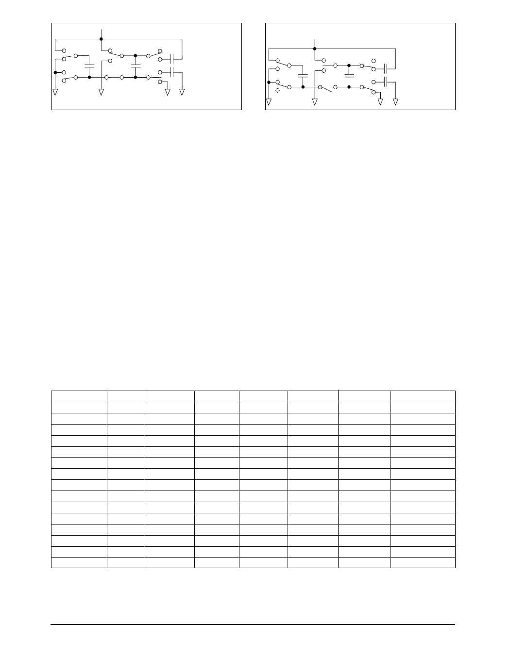
VCC = +5V
+
C1 –
–5V
+5V
+
C2 –
–5V
C4
+ – VDD Storage Capacitor
– + VSS Storage Capacitor
C3
Figure 4. Charge Pump Phase 3.
VCC = +5V
+
C1 –
+10V
+
C2 –
C4
+ – VDD Storage Capacitor
– + VSS Storage Capacitor
C3
Figure 5. Charge Pump Phase 4.
power supplies should provide a power
supply sequence of: +l0V, then +5V, followed
by –l0V.
Drivers
The SP502 has six (6) drivers which can be
programmed in six different modes of opera-
tion. One of the drivers for the SP502 is inter-
nally connected to an internal receiver input to
make up a half-duplex configuration. As shown
in the Mode Diagrams, the driver input of the
half-duplex channel is shared with an adjacent
driver such that when one is active the other is
disabled.
Control for the mode selection is done via a
four–bit control word. The SP502 does not have
a latch; the control word must be externally
latched either high or low to write the appropri-
ate code into the SP502. The drivers are pre-
arranged such that for each mode of operation
the relative position and functionality of the
drivers are set up to accommodate the selected
interface mode. As the mode of the drivers is
changed, the electrical characteristics will change
to support the requirements of clock, data, and
control line signal levels. Table 1 shows a sum-
mary of the electrical characteristics of the driv-
ers in the different interface modes. Unused
driver inputs can be left floating; however, to
ensure a desired state with no input signal, pull–
up resistors to +5V or pull–down resistors to
ground are suggested. Since the driver inputs
are both TTL or CMOS compatible, any value
resistor less than 100kΩ will suffice.
There are three basic types of driver circuits —
RS-232, RS-423, and RS-485. The RS-232 driv-
ers output a minimum of ±5V level single–ended
signals (with 3kΩ and 2500pF loading), and
Pin Label
Mode:
RS-232
V.35
TDEC3–TDEC0
SD(a)
0000
tri–state
0010
RS-232
1110
V.35–
SD(b)
tri–state
tri–state
V.35+
TR(a)
tri–state
RS-232
RS-232
TR(b)
tri–state
tri–state
tri–state
RS(a)
tri–state
RS-232
RS-232
RS(b)
tri–state
tri–state
tri–state
RL(a)
tri–state
RS-232
RS-232
RL(b)
tri–state
tri–state
tri–state
LL(a)
tri–state
RS-232
RS-232
LL(b)
tri–state
tri–state
tri–state
ST(a)
tri–state
RS-232
V.35–
ST(b)
tri–state
tri–state
V.35+
TT(a)
tri–state
RS-232
V.35–
TT(b)
tri–state
tri–state
V.35+
*The ST and TT driver outputs cannot be enabled simultaneously.
Table 1. SP502 Drivers
RS-422
0100
RS-422–
RS-422+
RS-422–
RS-422+
RS-422–
RS-422+
RS-422–
RS-422+
RS-422–
RS-422+
RS-422–
RS-422+
RS-422–
RS-422+
RS-485
0101
RS-485–
RS-485+
RS-485–
RS-485+
RS-485–
RS-485+
RS-485–
RS-485+
RS-485–
RS-485+
RS-485–
RS-485+
RS-485–
RS-485+
RS-449
1100
RS-422–
RS-422+
RS-422–
RS-422+
RS-422–
RS-422+
RS-423
tri–state
RS-423
tri–state
RS-422–
RS-422+
RS-422–
RS-422+
EIA-530
1101
RS-422–
RS-422+
RS-422–
RS-422+
RS-422–
RS-422+
RS-423
tri–state
RS-423
tri–state
RS-422–
RS-422+
RS-422–
RS-422+
Rev. 7/21/03
SP502 Multi-Mode Serial Transceiver
10
© Copyright 2003 Sipex Corporation
Share Link: 