SR3040C View Datasheet(PDF) - Willas Electronic Corp.
Part Name
Description
Manufacturer
SR3040C Datasheet PDF : 2 Pages
| |||
WILLAS
30.0A SCHOTTKY BARRIER RECTIFIERS -40V- 200V
1.0A SURFACE MOUNT SCHOTTKY BATROR- I2E4R7REPCATCIFKIEARGSE-20V- 200V
SOD-123+ PACKAGE
SR30F4M01C20-M+
THRUTHRU
SR30F2M0102C00-M+
Pb Free Product
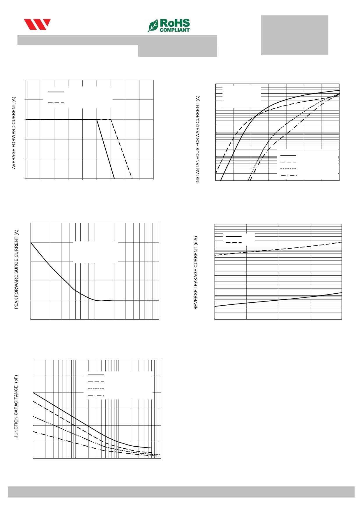
FIG. 1-TYPICAL FORWARD CURRENT DERATING CURVE
Features
50 • Batch process design, excellent power dissipation offers
better reverse leakage current and thermal resistance.
• Low profile sSRu3r0fa40cCe~SmR3o0u10n0tCed application in order to
40
optimize board space.
• Low power lSoRs3s0,15h0iCg~hSRe3f0f2ic00ieCncy.
• High current capability, low forward voltage drop.
30
• High surge capability.
• Guardring for overvoltage protection.
• Ultra high-speed switching.
20 • Silicon epitaxial planar chip, metal silicon junction.
• Lead-free parts meet environmental standards of
MIL-STD-19500 /228
10
• RoHS product for packing code suffix "G"
Halogen free product for packing code suffix "H"
Mechanical data
0 • Epoxy : UL94-V0 rated flame retardant
0
20
40
60
80 100 120 140 160 180
• Case : MoldedCApSlaEsTtiEcM, SPEORDA-T1U2R3EH(℃)
,
• Terminals :Plated terminals, solderable per MIL-STD-750
Method 2026
FIG. 3-MAXIMUM NON-REPETITIVE FORWARD SURGE CURRENT
• Polarity : Indicated by cathode band
FPIGa. 2c-TkYaPIgCAeLoFOuRtWliAnReD CHARACTERISTICS
100.00
10.00
SOD-123H
TJ=25℃ PULSE
WIDTH 300us 2%
DUTY CYCLE0.146(3.7)
0.130(3.3)
0.012(0.3) Typ.
1.00
0.071(1.8)
0.056(1.4)
0.10
0.01
0.2
0.3
0.031(0.8) Typ.
SR3040C
SR3060C
SR30100C
0.040(1S.R0)30150C~SR30200C
0.024(0.6)
0.4
0.5
0.6
0.7
0.8
0.9
FORWARD VOLT0A.0G3E1(0(.V8))Typ.
FIG. 4-TYPICAL REVERSE CHARACTERISTICS
Dimensions in inches and (millimeters)
250 • Mounting Position : Any
100.00
• Weight : Approximated 0.011 gram
25℃
200
MAXIMUM RATINGS AND ELECTRICAL CHARACTERISTICS
100℃
TJ=25℃ 8.3ms Single
10.00
Ratings at 25℃ ambient tempHealrfaStiunreeWuanveless otherwise specified.
S1in50gle phase half wave, 60HzJ,ErDeEsCismtivetehoodf inductive load.
For capacitive load, derate current by 20%
1.00
100
Marking Code
RATINGS
SYMBOL FM120-MH FM130-MH FM140-MH FM150-MH FM160-MH FM180-MH FM1100-MH FM1150-MH FM1200-MH UNIT
12
13
14
15
16
18
10
115 120
Maximum Recurrent Peak Reverse Voltage
Ma5x0imum RMS Voltage
VRRM
20
30
40
50
60
0.10
VRMS
14
21
28
35
42
80
100
150
200 Volts
56
70
105
140 Volts
Maximum DC Blocking Voltage
VDC
20
30
40
50
60
80
100
150
200 Volts
Maximum Average Forward Rectified Current
IO
0
1
10
Peak
Forward
Surge
Current 8.3 ms single half sine-wave
NUMBER OF CYCLES AT 60Hz
IFSM
superimposed on rated load (JEDEC method)
Typical Thermal Resistance (Note 2)
FIGT.y5p-icTaYl PJuICncAtiLonJUCNapCaTcIitOanNceCA(NPoAteC1IT) ANCE
RΘJA
CJ
Op30e0ra0 ting Temperature Range
Storage Temperature Range
TJ
TSTG
0.01
100
20
-55 to +125
1.0
Amps
40
60
80
100
PERCE3N0TAGE RATED PEAK REVERSE VOLTAGE (%) Amps
40
120
- 65 to +175
-55 to +150
℃/W
PF
℃
℃
2500
SR3040C
CHARACTERISTICS
SYMBOL FM120-MH FM130-MH FM140-MH FM150-MH FM160-MH FM180-MH FM1100-MH FM1150-MH FM1200-MH UNIT
SR3060C
Maximum Forward Voltage at 1.0A DC
VF
0.50
0.70
0.85
0.9
0.92 Volts
SR30100C
Ma20x0im0 um Average Reverse Current at @TSAP=R20515℃0C~SR302I0R0C
0.5
mAmps
Rated DC Blocking Voltage
@T A=125℃
10
1500
NOTES:
1- Measured at 1 MHZ and applied reverse voltage of 4.0 VDC.
2- T10h0e0rmal Resistance From Junction to Ambient
500
0
0
1
10
100
REVERSE VOLTAGE (V)
2012-06
2012-09
WILLAS ELECTRONIC CORP.
WILLAS ELECTRONIC CORP.
Share Link: 