M36W432BG-ZA View Datasheet(PDF) - STMicroelectronics
Part Name
Description
Manufacturer
M36W432BG-ZA
STMicroelectronics

M36W432BG-ZA Datasheet PDF : 66 Pages
| |||
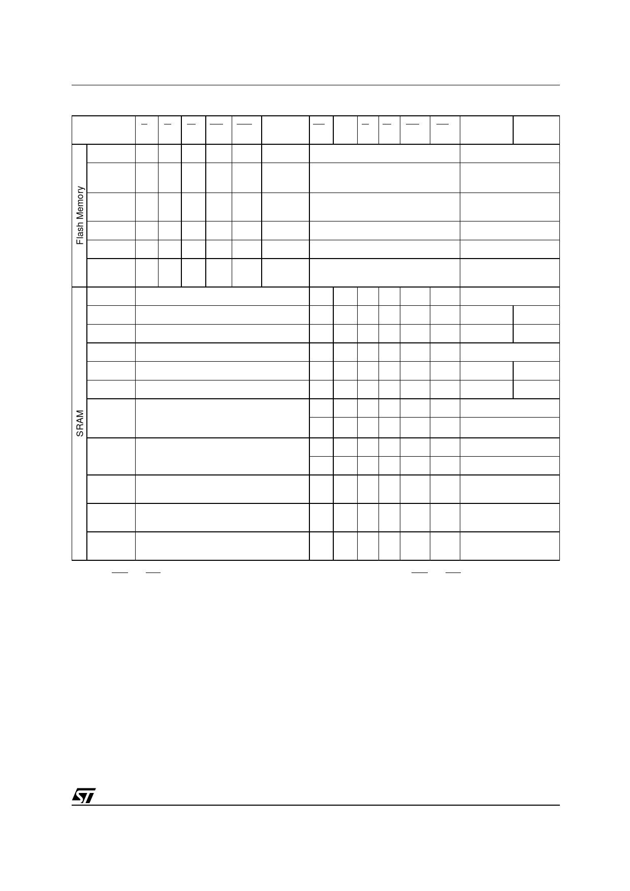
M36W432TG, M36W432BG
Table 2. Main Operation Modes
Operation
Mode
EF GF WF RPF WPF
VPPF
E1S E2S GS WS UBS LBS DQ15-DQ8 DQ7-DQ0
Read
VIL VIL VIH VIH X Don’t care
SRAM must be disabled
Data Output
Write
VIL VIH VIL VIH
X
VDDF or
VPPFH
SRAM must be disabled
Data Input
Block
Locking
VIL X X VIH VIL Don’t care
SRAM must be disabled
X
Standby VIH X X VIH X Don’t care Any SRAM mode is allowed
Hi-Z
Reset
X X X VIL X Don’t care Any SRAM mode is allowed
Hi-Z
Output
Disable
VIL VIH VIH VIH X Don’t care
Any SRAM mode is allowed
Hi-Z
Read
Flash must be disabled
VIL VIH VIL VIH VIL VIL Data out Word Read
Read
Flash must be disabled
VIL VIH VIL VIH VIL VIH Data out
Hi-Z
Read
Flash must be disabled
VIL VIH VIL VIH VIH VIL
Hi-Z Data out
Write
Flash must be disabled
VIL VIH X VIL VIL VIL Data in Word Write
Write
Flash must be disabled
VIL VIH X VIL VIH VIL
Data in
Hi-Z
Write
Flash must be disabled
VIL VIH X VIL VIL VIH
Hi-Z
Data in
Standby/
VIH VIL X X X
X
Hi-Z
Power
Any Flash mode is allowable
Down
X X X X VIH VIH
Hi-Z
Data
Retention
Any Flash mode is allowable
VIH VIL X X X
X
X X X X VIH VIH
Hi-Z
Hi-Z
Output
Disable
Any Flash mode is allowable
VIL VIH VIH VIH VIL VIL
Hi-Z
Output
Disable
Any Flash mode is allowable
VIL VIH VIH VIH VIL VIH
Hi-Z
Output
Disable
Any Flash mode is allowable
VIL VIH VIH VIH VIH VIL
Hi-Z
Note: 1. X = Don’t Care = VIL or VIH, VPPFH = 12V ± 5%.
2. If UBS and LBS are tied together the bus is at 16 bit. For an 8 bit bus configuration use UBS and LBS separately.
11/66
Share Link: