CS5253-1 View Datasheet(PDF) - Cherry semiconductor
Part Name
Description
Manufacturer
CS5253-1 Datasheet PDF : 9 Pages
| |||
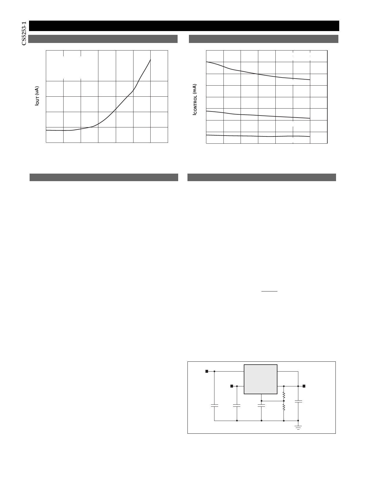
Typical Performance Characteristics: Continued
VPOWER Only Output Current vs Junction Temperature
VCONTROL Supply Current vs Junction Temperature
30
VPOWER = 6V
25
VOUT = 0V
VCONTROL not connected
20
40
VCONTROL = 2.75V
VPOWER = 2.05V
35
30
IOUT = 3A
25
15
20
10
5
00
20
40
60
80
100
120
140
Junction Temperature (C)
15
10
IOUT = 1A
5
IOUT = 100mA
0
0
20
40
60
80
100
120
140
Junction Temperature (C)
Theory of Operation
Design Guidelines
The CS5253-1 linear regulator provides adjustable voltages
from 1.26V to 5V at currents up to 3A. The regulator is pro-
tected against short circuits, and includes a thermal shut-
down circuit with hysteresis. The output, which is current
limited, consists of a PNP-NPN transistor pair and requires
an output capacitor for stability. A detailed procedure for
selecting this capacitor is included in the Stability
Considerations section.
VPOWER Function
The CS5253-1 utilizes a two supply approach to maximize
efficiency. The collector of the power device is brought out
to the VPOWER pin to minimize internal power dissipation
under high current loads. VCONTROL provides for the con-
trol circuitry and the drive for the output NPN transistor.
VCONTROL should be at least 1V greater than the output
voltage. Special care has been taken to ensure that there are
no supply sequencing problems. The output voltage will
not turn on until both supplies are operating. If the control
voltage comes up first, the output current will be limited to
about three milliamperes until the power input voltage
comes up. If the power input voltage comes up first, the
output will not turn on at all until the control voltage
comes up. The output can never come up unregulated.
The CS5253-1 can also be used as a single supply device
with the control and power inputs tied together. In this
mode, the dropout will be determined by the minimum
control voltage.
Output Voltage Sensing
The CS5253-1 five terminal linear regulator includes a ded-
icated VSENSE function. This allows for true Kelvin sensing
of the output voltage. This feature can virtually eliminate
errors in the output voltage due to load regulation.
Regulation will be optimized at the point where the sense
pin is tied to the output.
Adjustable Operation
This LDO adjustable regulator has an output voltage range
of 1.26V to 5V. An external resistor divider sets the output
voltage as shown in Figure 1. The regulatorÕs voltage sens-
ing error amplifier maintains a fixed 1.260V reference
between the output pin and the adjust pin.
A resistor divider network R1 and R2 causes a fixed current
to flow to ground. This current creates a voltage across R2
that adds to the 1.260V across R1 and sets the overall out-
put voltage. The adjust pin current (typically 50µA) also
flows through R2 and adds a small error that should be
taken into account if precise adjustment of VOUT is neces-
sary. The output voltage is set according to the formula:
VOUT = 1.260V ´
R1+R2
R1
+ R2 ´ IADJ
The term IADJ ´ R2 represents the error added by the adjust
pin current. R1 is chosen so that the minimum load current
is at least 10mA. R1 and R2 should be of the same composi-
tion for best tracking over temperature. The divider resis-
tors should be placed physically as close to the load as pos-
sible.
5V
VCONTROL VOUT
CS5253-1
3.3V
VPOWER VSENSE
Adjust
R1
2.5V
@3A
R2
Figure 1: Typical application schematic. The resistor divider sets VOUT,
with the internal 1.260V reference dropped across R1.
6
Share Link: 