ACT5101-1 View Datasheet(PDF) - Aeroflex Corporation
Part Name
Description
Manufacturer
ACT5101-1 Datasheet PDF : 12 Pages
| |||
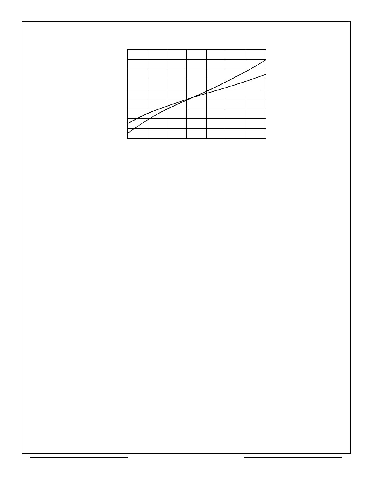
2.8
2.6
TJ = 150°C
2.4
VCE 2.2
(V) 2.0
1.8
TJ = 25°C
1.6
1.4
1.2
1.0
10
20
30
40
50
60
70
80
IC (A)
FIGURE 4 - IGBT COLLECTOR-TO-EMITTER VOLTAGE VS. COLLECTOR CURRENT
Based upon this voltage drop and the conduction duty cycle a conduction power loss may be calculated
as:
Pc = δS ⋅ δPWM ⋅ VCE ⋅ IC
where:
pc =
Conduction IGBT Power Dissipation
δs =
Switch Duty Cycle, (.33 for brushless drives in run condition, 1 in stall)
δPWM = PWM on/off ratio
VCE =
Collector Emitter voltage from Figure 4 for a particular collector current
IC =
Collector current
Switching losses are dependent upon the operating frequency, collector current and again duty cycle as:
where:
Ps =
Eon =
Eoff =
fo =
IC =
Ps
=
δS
⋅
[Eon
+
Eoff]
⋅
fo
⋅
-I--C--
40
Switching IGBT Power Dissipation
Turn on energy loss from Table 2
Turn off energy loss from Table 2
Pulse width modulation frequency
Collector current
Commutation diode losses are calculated as:
Pd = δs ⋅ [1 – δPWM] ⋅ Vf ⋅ If
Aeroflex Circuit Technology
7
SCD5101-1 REV D 5/14/01 Plainview NY (516) 694-6700
Share Link: 