INT201PF1 View Datasheet(PDF) - Power Integrations, Inc
Part Name
Description
Manufacturer
INT201PF1 Datasheet PDF : 12 Pages
| |||
INT201
HV+
C2
D1
VDD
C1
CONTROL
8
76
5
INT201
1
23
4
R2
Q2
8
76
5
INT202
1
23
4
R1
Q1
D3
PHASE 1
D2
PHASE 2
3-PHASE
SRM
PHASE 3
HV-
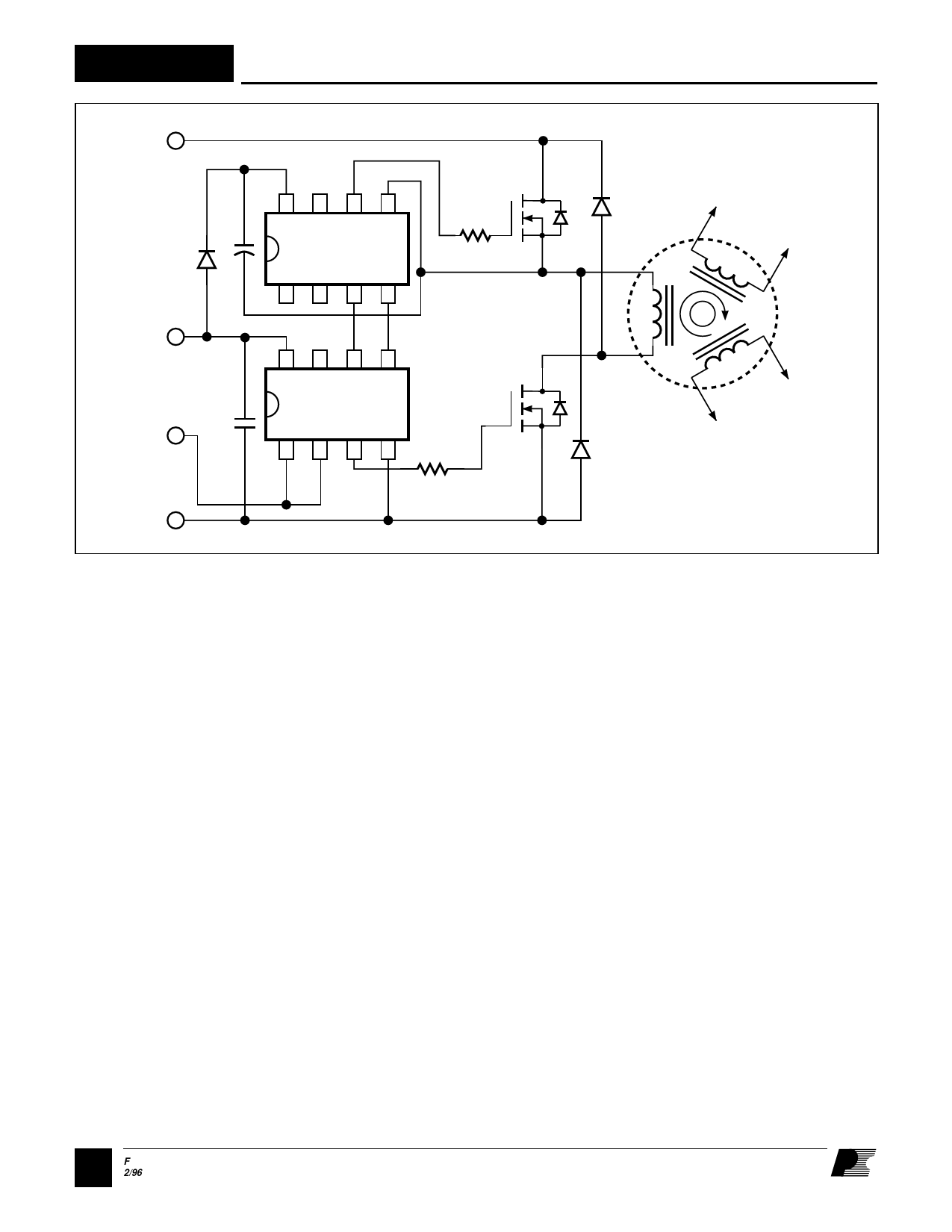
Figure 6. Using the INT202 and INT201 to Drive a Switched Reluctance Motor.
PI-1468-042695
General Circuit Operation (cont.)
The bootstrap capacitor must be large
enough to provide bias current over the
entire on time interval of the high-side
driver without significant voltage sag or
decay. The MOSFET gate charge must
also be supplied at the desired switching
frequency. Figure 5 shows the maximum
high-side on time versus gate charge of
the external MOSFET. Applications
with extremely long high-side on times
require special techniques discussed in
AN-10.
A three-phase switched reluctance motor
example using the INT202/201 is given
in Figure 6. The LS IN signal directly
controls MOSFET Q1. Unlike the
INT200, the INT202 allows both the
low and high-side drivers to be on at the
same time, as this is required in
applications where the load is placed
between the low and high-side output
MOSFETs.
4F
2/96
Share Link: 