INT201PF1 View Datasheet(PDF) - Power Integrations, Inc
Part Name
Description
Manufacturer
INT201PF1 Datasheet PDF : 12 Pages
| |||
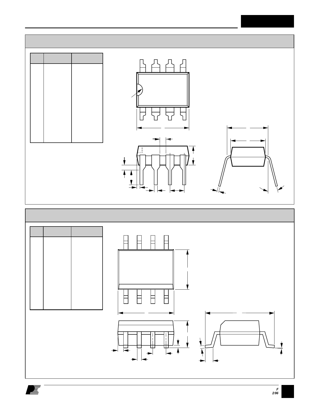
P08A
Dim. inches
mm
A .395 MAX 10.03 MAX
B .090-.110
2.29-2.79
C .015-.021
0.38-0.53
D .040 TYP
E .015-.030
1.02 TYP
0.38-0.76
F
.125 MIN
3.18 MIN
G .015 MIN
0.38 MIN
H .125-.135
3.18-3.43
J
.300-.320
7.62-8.13
K .245-.255
6.22-6.48
L .009-.015
0.23-0.38
Notes:
1. Package dimensions conform to JEDEC
specification MS-001-AB for standard dual in-
line (DIP) package .300 inch row spacing
(PLASTIC) 8 leads (issue B, 7/85).
2. Controlling dimensions: inches.
3. Dimensions are for the molded body and do
not include mold flash or other protrusions.
Mold flash or protrusions shall not exceed .010
inch (.25 mm) on any side.
4. These dimensions measured with the leads
constrained to be perpendicular to package
bottom.
5. Pin 1 orientation identified by end notch or
dot adjacent to Pin 1.
8
5
Note 5
1
4
A (3)
D
H
GF
E
L
C
B
T08A
DIM inches
mm
8
5
A 0.189-0.197 4.80-5.00
B 0.050 TYP
1.27 TYP
C 0.014-0.019 0.35-0.49
D 0.012 TYP
E 0.053-0.069
0.31 TYP
1.35-1.75
(3)
K
F 0.004-0.010 0.10-0.25
G 0.228-0.244 5.80-6.20
H 0.007-0.010 0.19-0.25
J 0.021-0.045 0.51-1.14
K 0.150-0.157 3.80-4.00
1
(3)
4
A
Notes:
1. Package dimensions conform to JEDEC
specification MS-012-AA for standard small
outline (SO) package, 8 leads, 3.75 mm
(.150 inch) body width (issue A, June 1985).
2. Controlling dimensions are in mm.
E
3. Dimensions are for the molded body
H
and do not include mold flash or
protrusions. Mold flash or protrusions
shall not exceed .15 mm (.006 inch) on any
side.
D
B
4. Pin 1 side identified edge by chamfer on
F
top of the package body or indent on Pin 1
C
J
end.
INT201
Plastic DIP-8
J
(4)
K (3)
0 – 15 °
PI-1842-050196
Plastic SO-8
G
0-8˚ TYP.
PI-1845-050196
9 F
2/96
Share Link: 