MC33091AD View Datasheet(PDF) - Motorola => Freescale
Part Name
Description
Manufacturer
MC33091AD Datasheet PDF : 16 Pages
| |||
MC33091A
ELECTRICAL CHARACTERISTICS (Values are noted under conditions of 7.0 V ≤ VCC ≤ 24 V, –40°C ≤ TA ≤ +125°C, unless otherwise
noted. Typical values reflect approximate mean at TA = 25°C at time of device characterization.)
Characteristics
Symbol
Min
Typ
Max
Unit
Supply Current (Note 1)
Vin = 0 V
Vin = 5.0 V (RX = 100 k)
Supply Clamp Voltage (Note 2)
Gate–to–Source Voltage Range (Pin 4)
Gate Current (Pin 4)
VG = VCC
Gate Saturation Voltage (IG = 10 µA)
Short Circuit Gate Voltage (Note 4)
Input Control Threshold Voltage (Pin 7)
Input Control Current (Pin 7) (Vin = 5.0 V)
Timer Current Constant (Pin 8)
(RX = 100 k, VT = 0, VDS = 1.0 V) (Note 3)
Timer (Pin 8)
Lower Threshold Voltage
Upper Threshold Voltage
Fault Sink Current (Pin 6)
VF = 5.0 V
VF = 0
Fault Saturation Voltage (Pin 6) (IF = 500 µA)
ICC
–
160
300
µA
–
2.5
6.0
mA
VZ
VGS
IG
29
–
35
V
8.0
12
15
V
µA
30
–
400
VG(sat)
0
1.2
1.4
V
IGC
6.4
7.0
7.7
V
V
VIL
–
2.7
1.5
VIH
3.5
2.7
–
Iin
–
100
250
µA
K
µA/V2
0.7
1.1
1.5
VTL
VTH
V
0.4
0.95
1.2
4.3
4.6
5.2
IOL
IOH
VOL
500
–
–
µA
–
2.0
100
nA
–
0.2
0.8
V
NOTES: 1. The total supply current into Pin 2 and Pin 5 with RX = 100 k (from Pin 2 to supply) and 45 k pull–up resistor from Pin 6 to supply.
2. An internal zener clamp is provided to protect the device from overvoltage transients on the supply line.
3. The timer current constant is the proportionality constant of the voltage to current converter used to monitor the VDS voltage developed across the
FET (from Pin 1 to the supply).
4. The gate voltage will be clamped at approximately 7.0 V above the source voltage whenever the source voltage is less than approximately 1.0 V
above ground.
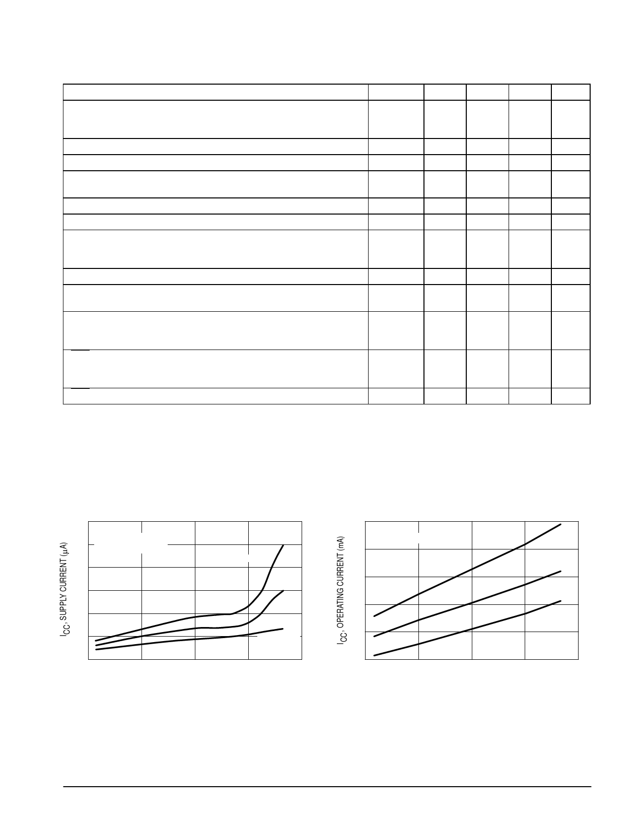
Figure 2. Supply Current versus Supply Voltage
600
500
Vin = 0 V (Gate “off”)
VDS = 2.0 V
400
TA = –40°C
300
200
100
0
6.0
TA = 25°C
TA = 125°C
12
18
24
30
VCC, SUPPLY VOLTAGE (V)
Figure 3. Operating Current versus Supply Voltage
6.0
Vin = 5.0 V (Gate “on”)
5.0
TA = –40°C
4.0
TA = 25°C
3.0
TA = 125°C
2.0
1.0
6.0
12
18
24
30
VCC, SUPPLY VOLTAGE (V)
MOTOROLA ANALOG IC DEVICE DATA
3
Share Link: 