E-L6258 View Datasheet(PDF) - STMicroelectronics
Part Name
Description
Manufacturer
E-L6258 Datasheet PDF : 32 Pages
| |||
PWM current control loop
Verr_out = -(ic · Zc) so ic = -(Verr_out ·
--1----
Zc
)
because ib = icwe have:
Vsense ·
---1----
Rb
= -(Verr_out ·
--1----
Zc
)
Bx = –V-----e----r--r--_----o---u---t = –-Z----c--
Vsense Rb
L6258
In the case of no external RC network is used to compensate the error amplifier, the typical
open loop transfer function of the error plus the sense amplifier is something with a gain
around 80dB and a unity gain bandwidth at 400kHz. In this case the situation of the total
transfer function Aloop, given by the sum of the AxdB and BxdB is:
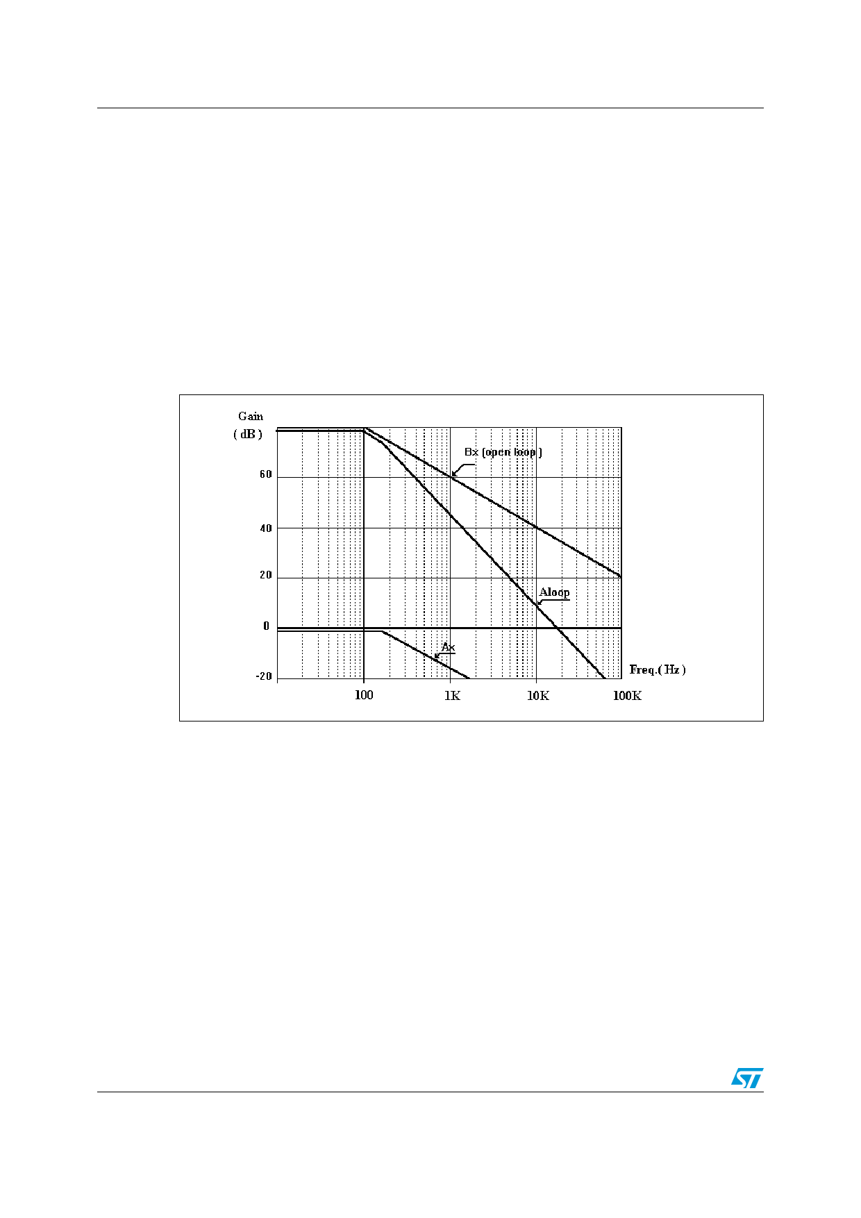
Figure 8. Aloop bode plot (uncompensated)
The BODE diagram shows together the error amplifier open loop transfer function, the Ax
function and the resultant total Aloop given by the following equation:
AloopdB = AxdB + BxdB
The total Aloop has an high DC gain of 78.1dB with a bandwidth of 15KHz, but the problem
in this case is the stability of the system; in fact the total Aloop cross the zero dB axis with a
slope of -40dB/decade.
Now it is necessary to compensate the error amplifier in order to obtain a total Aloop with an
high DC gain and a large bandwidth. Aloop must have enough phase margin to guarantee
the stability of the system.
A method to reach the stability of the system, using the RC network showed in the block
diagram, is to cancel the load pole with the zero given by the compensation of the error
amplifier.
The transfer function of the Bx block with the compensation on the error amplifier is:
20/32
Share Link: 