TDA9143/N1 View Datasheet(PDF) - Philips Electronics
Part Name
Description
Manufacturer
TDA9143/N1
Philips Electronics

TDA9143/N1 Datasheet PDF : 40 Pages
| |||
Philips Semiconductors
I2C-bus controlled, alignment-free
PAL/NTSC/SECAM decoder/sync processor
Preliminary specification
TDA9143
detector threshold in two consecutive fields, noise is
indicated and bus bit SNR is set.
The free-running frequency of the oscillator is determined
by a digital control circuit that is locked to the active crystal.
When a power-on-reset pulse is detected the frequency of
the oscillator is switched to a frequency of about 10 MHz
(23 kHz horizontal frequency) to protect the horizontal
output transistor. The oscillator frequency is calibrated to
6.875 MHz or 6.75 MHz after receiving data on
subaddress 01 for the first time after power-on-reset
detection.
To ensure that this procedure does not fail it is absolutely
necessary to send subaddress 00 before subaddress 01.
Subaddress 00 contains the crystal indication bits and
when subaddress 01 is received the line oscillator
calibration will be initiated (for the start-up procedure after
power-on-reset detection, see the I2C-bus protocol). The
calibration is terminated when the oscillator frequency
reaches 6.875 MHz or 6.75 MHz.
The ϕ1 loop can be opened using the I2C-bus. This is to
facilitate On Screen Display (OSD) information. If there is
no input signal or a very noisy input signal, the ϕ1 loop can
be opened to provide a stable line frequency, and thus a
stable picture.
The sync part also delivers a two-level sandcastle signal,
which provides a combined horizontal and vertical
blanking signal and a clamping pulse for the display
section of the TV.
MACROVISION sync gating
A dedicated gating signal for the separated sync pulses,
starting 11 lines after the detection of a vertical sync pulse
until picture scan starts, can be used to improve the
behaviour of the horizontal PLL with respect to the
unwanted disturbances caused by the pseudo-sync pulses
in video signals with MACROVISION anti-copy guard
signals. This sync gating excludes the pseudo-sync pulses
and can only take place in the auto and fast ϕ1 time
constant mode, provided I2C-bus bit SNR = 0 and I2C-bus
bit EMG = 1. I2C-bus bit EMG = 1 enables and EMG = 0
disables this sync gating in the horizontal PLL.
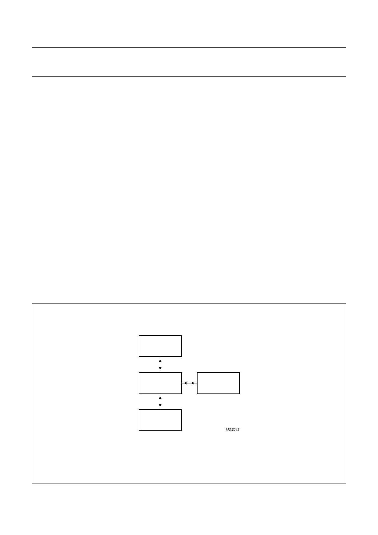
Vertical divider system
The vertical divider system has a fully integrated vertical
sync separator.
The divider can accommodate both 50 Hz and 60 Hz
systems; it can either determine the field frequency
automatically or it can be forced to the desired system via
the I2C-bus. A block diagram of the vertical divider system
is illustrated in Fig.4.
1996 Jan 17
handbook, halfpage
LINE COUNTER
CONTROLLER
TIMING
GENERATOR
NORM COUNTER
MGE043
Fig.4 Block diagram of the vertical divider system.
9
Share Link: