LTC1041 View Datasheet(PDF) - Linear Technology
Part Name
Description
Manufacturer
LTC1041 Datasheet PDF : 8 Pages
| |||
ELECTRICAL CHARACTERISTICS
( ) Note 3: SET POINT error ≡ VU + VL – SET POINT
2
where VU = upper band limit and VL = lower band limit.
Note 4: Deadband error ≡ (VU – VL) – 2 • DELTA where VU = upper band
limit and VL = lower band limit.
LTC1041
Note 5: RIN is guaranteed by design and is not tested.
RIN = 1/(fS x 66pF).
Note 6: Average supply current = tD • IS(ON) • fS + (1 – tD • fS) lS(OFF).
Note 7: Response time is set by an internal oscillator and is independent
of overdrive voltage. tD = VP-P pulse width.
Note 8: Output also capable of meeting EIA/JEDEC standard B series
CMOS drive specifications.
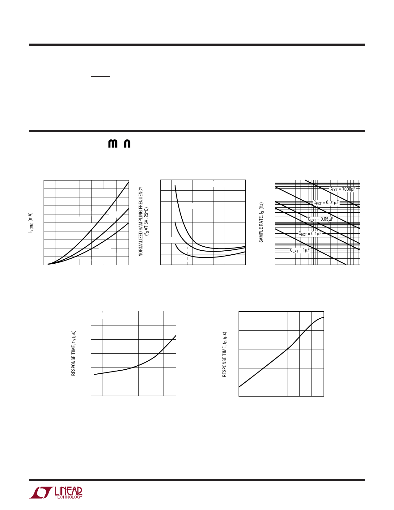
TYPICAL PERFOR A CE CHARACTERISTICS
IS(ON) vs V+
20
18
16
14
12
25°C
10
–55°C
8
6
4
125°C
2
0
2 4 6 8 10 12 14 16
SUPPLY VOLTAGE, V+ (V)
LTC1041 • TPC01
Normalized Sampling
Frequency vs V+, Temperature
2.2
R = 1M, C = 0.1µF
2.0
1.8
TA = 125°C
1.6
1.4
1.2
1.0 TA = 25°C
0.8
0.6
0
TA = – 55°C
2 4 6 8 10 12 14 16
SUPPLY VOLTAGE, V+ (V)
LTC1041 • TPC02
Sampling Rate vs REXT, CEXT
103
CEXT = 1000pF
102
CEXT = 0.01µF
10
CEXT = 0.05µF
CEXT = 0.1µF
1
CEXT = 1µF
0.1
100k
1M
REXT (Ω)
10M
LTC1041 • TPC03
Response Time
vs Supply Voltage
300
TA = 25°C
250
200
150
100
50
0
2 4 6 8 10 12 14 16
SUPPLY VOLTAGE, V+ (V)
LTC1041 • TPC04
Response Time
vs Temperature
130 V+ = 5V
120
110
100
90
80
70
60
50
40
–50
–25 0 25 50 75 100 125
AMBIENT TEMPERATURE, TA (°C)
LTC1041 • TPC05
1041fa
3
Share Link: 