Q62703-Q1087 View Datasheet(PDF) - OSRAM GmbH
Part Name
Description
Manufacturer
Q62703-Q1087 Datasheet PDF : 9 Pages
| |||
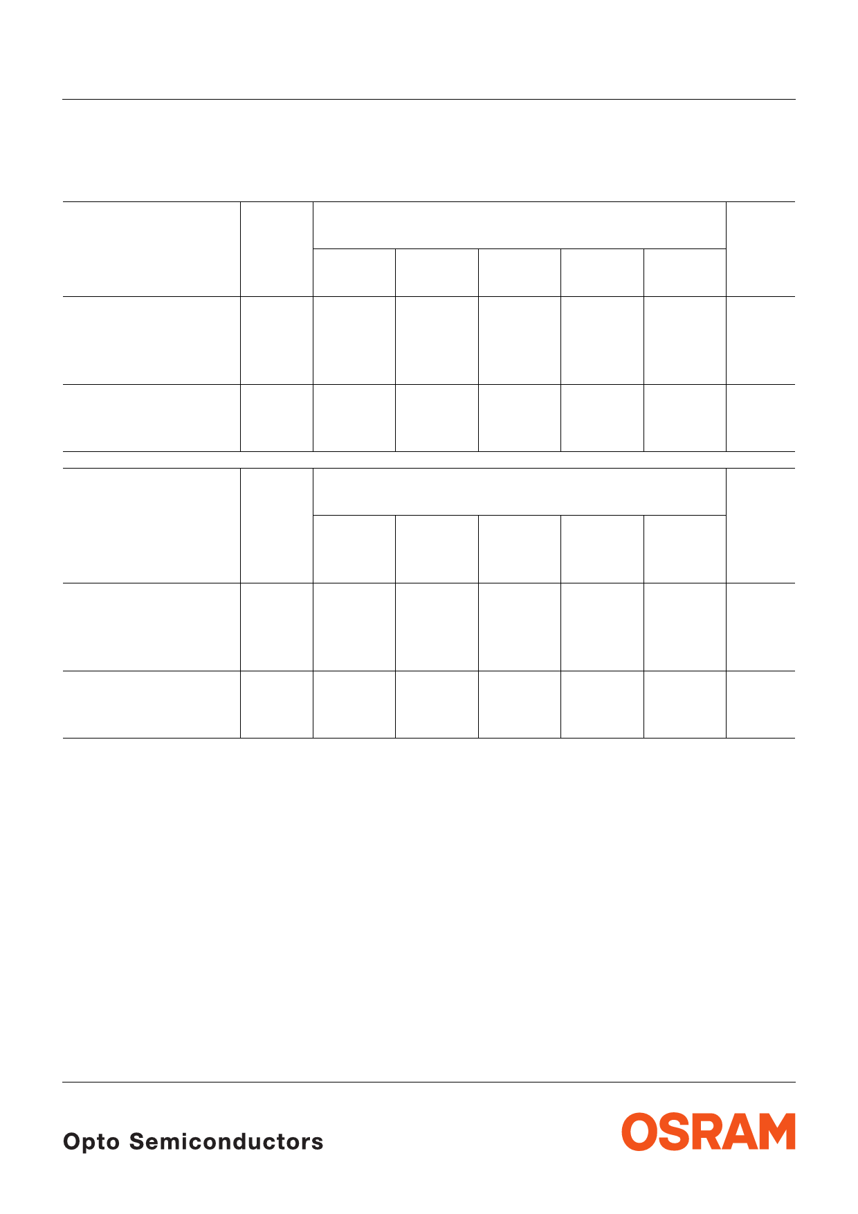
SFH 480, SFH 481, SFH 482
Gruppierung der Strahlstärke Ie in Achsrichtung
gemessen bei einem Raumwinkel Ω = 0.01 sr
Grouping of Radiant Intensity Ie in Axial Direction
at a solid angle of Ω = 0.01 sr
Bezeichnung
Parameter
Symbol
Symbol
SFH
480-2
SFH
480-3
Strahlstärke
Radiant intensity
IF = 100 mA, tp = 20 ms
Strahlstärke
Radiant intensity
IF = 1 A, tp = 100 µs
Ie min
Ie max
Ie typ.
> 40
–
540
> 63
–
630
Wert
Value
SFH
481
SFH
481-1
≥ 10
10
–
20
220
130
SFH
481-2
16
–
220
Einheit
Unit
mW/sr
mW/sr
mW/sr
Bezeichnung
Parameter
Symbol
Symbol
Wert
Value
Einheit
Unit
SFH
482
SFH
482-1
SFH
482-2
SFH
482-3
SFH
482-M
E 78001)
Strahlstärke
Radiant intensity
IF = 100 mA, tp = 20 ms Ie min
≥ 3.15
3.15
5
8
Ie max
–
6.3
10
–
1.6 ... 3.2 mW/sr
–
mW/sr
Strahlstärke
Radiant intensity
IF = 1 A, tp = 100 µs
Ie typ.
–
40
65
80
–
mW/sr
1) Die Messung der Strahlstärke und des Halbwinkels erfolgt mit einer Lochblende vor dem Bauteil (Durchmesser der
Lochblende: 2.0 mm; Abstand Lochblende zu Gehäuserückseite: 5.4 mm). Dadurch wird sichergestellt, daβ bei der
Strahlstärkemessung nur diejenige Strahlung in Achsrichtung bewertet wird, die direkt von der Chipoberfläche
austritt. Von der Bodenplatte reflektierte Strahlung (vagabundierende Strahlung) wird dagegen nicht bewertet. Diese
Reflexionen sind besonders bei Abbildungen der Chipoberfläche über Zusatzoptiken störend (z.B. Lichtschranken
groβer Reichweite). In der Anwendung werden im allgemeinen diese Reflexionen ebenfalls durch Blenden
unterdrückt. Durch dieses, der Anwendung entsprechende Meβverfahren ergibt sich für den Anwender eine besser
verwertbare Gröβe. Diese Lochblendenmessung ist gekennzeichnet durch den Eintrag „E 7800“, der an die
Typenbezeichnung angehängt ist.
1) An aperture is used in front of the component for measurement of the radiant intensity and the half angle (diameter
of the aperture: 1.1 mm; distance of aperture to case back side: 4 mm). This ensures that solely the radiation in axial
direction emitting directly from the chip surface will be evaluated during measurement of the radiant intensity.
Radiation reflected by the bottom plate (stray radiation) will not be evaluated. These reflections impair the projection
of the chip surface by additional optics (e.g. long-range light reflection switches). In respect of the application of the
component, these reflections are generally suppressed by apertures as well. This measuring procedure
corresponding with the application provides more useful values. This aperture measurement is denoted by “E 7800”
added to the type designation.
2001-10-01
5
Share Link: 