MAX837 View Datasheet(PDF) - Maxim Integrated
Part Name
Description
Manufacturer
MAX837 Datasheet PDF : 7 Pages
| |||
4-Pin Micropower Voltage Monitors
_____________________________Typical Operating Characteristics (continued)
(VCC = +5V, RLOAD = 1MΩ, RPULLUP = 10kΩ (MAX836 only), TA = +25°C, unless otherwise noted.)
VCC FALLING PROPAGATION DELAY
vs. TEMPERATURE
160
1mV/μs
140
VTRIP = 4.63V
120
10mV/μs
100
80
VTRIP = 3.0V
VTRIP = 4.63V
60
VTRIP = 3.0V
40
-60 -40 -20 0 20 40 60
TEMPERATURE (°C)
80 100
1800
1600
1400
1200
1000
800
600
400
200
0
2
OUT RISE/FALL-TIME
vs. SUPPLY VOLTAGE
RISE TIME
MAX837 ONLY
FALL TIME
3 4 5 6 7 8 9 10 11 12
VCC (V)
_____________________Pin Description
PIN NAME
FUNCTION
1
GND System Ground
2
VCC
System Supply Input
Noninverting Input to the Comparator.
3
IN
The inverting input connects to the
internal 1.204V bandgap reference.
4
OUT
Open-Drain (MAX836) or
Push-Pull (MAX837) Output
GND
OUT
MAX836
VCC
RPULLUP
VCC
0.1μF
VCC
IN
VTRIP
=
(1.204)
R1
+ R2
R2
R1
R2
NOTE: UNITS ARE OHMS AND VOLTS
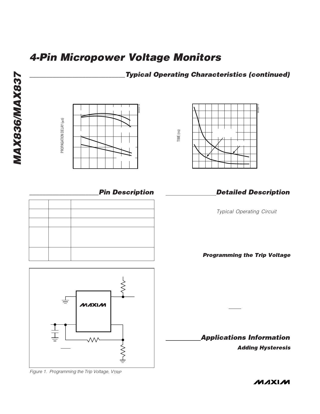
Figure 1. Programming the Trip Voltage, VTRIP
Detailed Description
The MAX836/MAX837 micropower voltage monitors
contain a 1.204V precision bandgap reference and a
comparator (see the Typical Operating Circuit). The
only difference between the two parts is the structure of
the comparator output driver. The MAX836 has an
open-drain n-channel output driver that can be pulled
up to a voltage higher than VCC, but under 11V. The
MAX837’s output is push-pull, and can both source
and sink current.
Programming the Trip Voltage
Two external resistors set the trip voltage, VTRIP (Figure 1).
VTRIP is the point at which the applied voltage (typically
VCC) toggles OUT. The MAX836/MAX837’s high input
impedance allows large-value resistors without compro-
mising trip-voltage accuracy. To minimize current con-
sumption, select a value for R2 between 500kΩ and
1MΩ, then calculate R1 as follows:
R1
=
R2
⎛
⎝⎜
VTRIP
VTH
⎞
- 1⎠⎟
where VTRIP = desired trip voltage (in volts), VTH =
threshold trip voltage (1.204V).
Applications Information
Adding Hysteresis
Hysteresis adds noise immunity to the MAX836/MAX837
and prevents repeated triggering when VIN is near the
threshold trip voltage. Figure 2 shows how to add hys-
teresis to the comparator. The technique is similar for
4 _______________________________________________________________________________________
Share Link: 