MAX837 View Datasheet(PDF) - Maxim Integrated
Part Name
Description
Manufacturer
MAX837 Datasheet PDF : 7 Pages
| |||
4-Pin Micropower Voltage Monitors
both parts. For the MAX836, select the ratio of resistors
R1 and R2 so that IN sees 1.204V when the monitor volt-
age falls to or rises above the desired trip point (VTRIP).
R3 adds hysteresis and is typically an order of magni-
tude larger than R1 or R2. The current through R1 and
R2 should be at least 500nA to ensure that the 12nA
maximum input current does not shift the trip point sig-
nificantly. Capacitor C1 adds additional noise rejection.
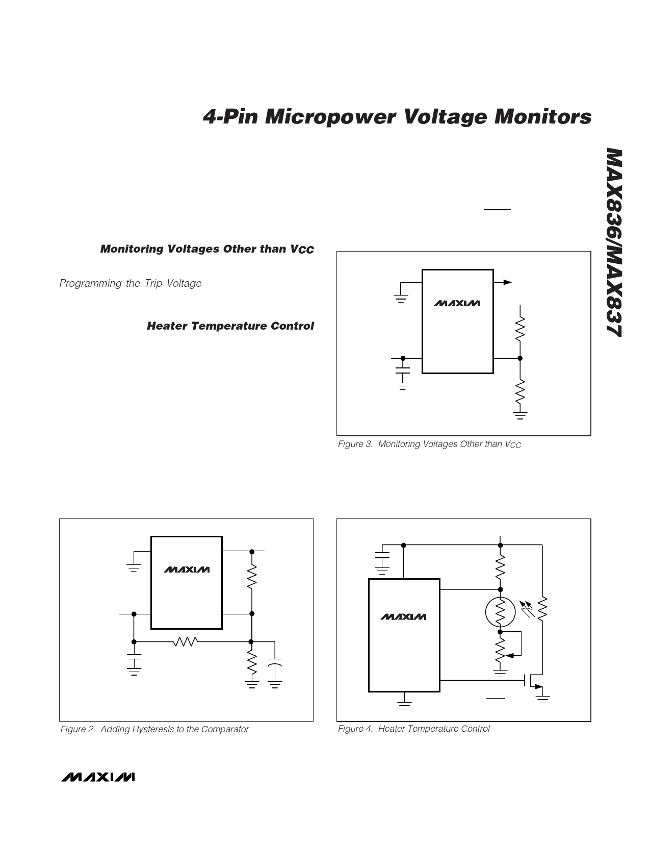
Monitoring Voltages Other than VCC
The MAX836/MAX837 can monitor voltages other than
VCC (Figure 3). Calculate VTRIP as shown in the
Programming the Trip Voltage section. The monitored
voltage (VMON) is independent of VCC. VIN must be 1V
less than VCC.
Heater Temperature Control
Figure 4 shows a basic heater temperature-control cir-
cuit. Upon power-up, OUT is high and the n-channel
MOSFET turns on. Current flows through the heating
element (R4), warming the surrounding area. R2 is a
negative-temperature-coefficient thermistor and as tem-
perature increases, its resistance decreases. As the
thermistor heats up and its resistance decreases, the
MAX837’s voltage at IN decreases until it reaches the
1.204V threshold voltage. At this point, OUT goes low,
turning off the heating element. The thermistor cools
and the voltage at IN rises until it overcomes the
MAX837’s hysteresis (6mV). OUT returns high when this
point is reached, turning on the heating element again.
This cycle repeats as long as power is applied.
Determine the thermistor’s resistance (R2) at the
desired temperature. Then, using R2’s resistance and
half the resistance of R3, calculate R1’s value with the
following formula:
R1
=
(R2
+
R3)
⎛
⎝⎜
VCC
1.204
⎞
- 1⎠⎟
VCC
0.1μF
GND
OUT
MAX837
VMON
R1
VCC
IN
R2
Figure 3. Monitoring Voltages Other than VCC
GND
OUT
MAX837
VCC
VCC
IN
OUT
R3
R1
0.1μF
R2
C1
NOTE: C1 ADDS ADDITIONAL NOISE IMMUNITY
Figure 2. Adding Hysteresis to the Comparator
VCC
0.1μF
R1
VCC
IN
THERMISTOR
R2
WITH
NEGATIVE
T
MAX837
COEFFICIENT
R3
HEATING
ELEMENT
R4
GND OUT
( ) R1 = (R2 + R3) VCC - 1 Ω
1.204
Figure 4. Heater Temperature Control
_______________________________________________________________________________________ 5
Share Link: 