TPSMB10A View Datasheet(PDF) - Littelfuse, Inc
Part Name
Description
Manufacturer
TPSMB10A Datasheet PDF : 6 Pages
| |||
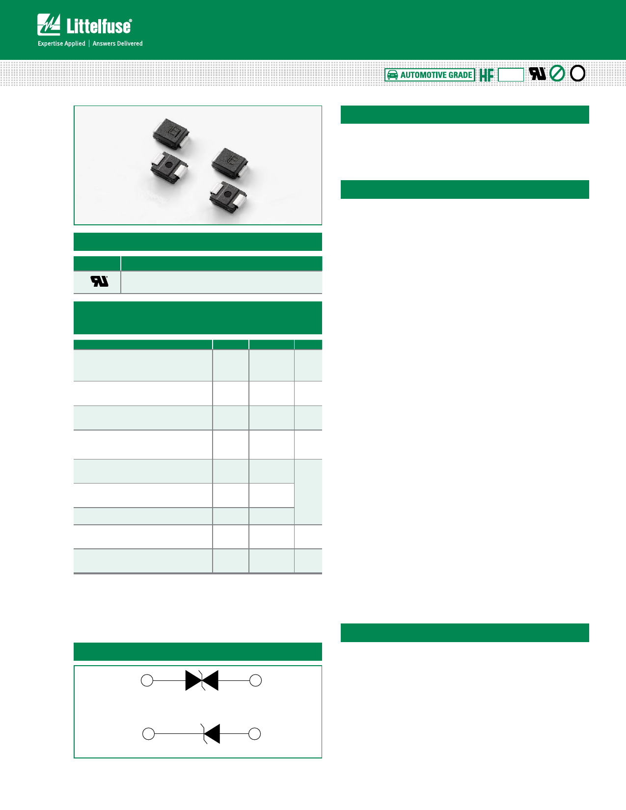
TPSMB Series
TVS Diodes
Surface Mount – 600W > TPSMB series
RoHS
Pb e3
Uni-directional
Bi-directional
Agency Approvals
AGENCY
AGENCY FILE NUMBER
E230531
Maximum Ratings and Thermal Characteristics
(TA=25OC unless otherwise noted)
Parameter
Symbol Value Unit
Peak Pulse Power Dissipation by
10/1000µs waveform
(Fig.1)(Note 1), (Note 2)
PPPM
600
W
Power Dissipation on infinite heat
sink at TL=50OC
PM(AV)
5.0
W
Peak Forward Surge Current, 8.3ms
Single Half Sine Wave (Note 3)
IFSM
100
A
Maximum Instantaneous Forward
Voltage at 50A for Unidirectional
only (Note 4)
Operating Junction Temperature
Range (VBR≤ 91V)
Operating Junction Temperature
Range (VBR > 91V)
VF
3.5
V
TJ
-65 to 175
TJ
-65 to 150 °C
Storage Temperature Range
TSTG -65 to 175
Typical Thermal Resistance Junction
to Lead
RθJL
20
°C/W
Typical Thermal Resistance Junction
to Ambient
RθJA
100 °C/W
Notes:
1. Non-repetitive current pulse, per Fig.4 and derated above TA=25ºC per Fig. 3.
2. Mounted on copper pad area of 0.2x0.2” (5.0 x 5.0mm) to each terminal.
3. Measured on 8.3ms single half sine wave or equivalent square wave for unidirectional
component only,duty cycle=4 per minute maximum.
4. VF < 3.5V for part number below 300A, VF < 5.0V for part number with 300A or above.
Functional Diagram
Cathode
Bi-directional
Uni-directional
Anode
Description
The TPSMB series is designed specifically to protect
sensitive electronic equipment from voltage transients
induced by lightning and other transient voltage events.
Features
• High reliability application • Fast response time:
and automotive grade AEC typically less than 1.0ns
Q101 qualified
from 0V to VBR min
• Surface mount component • Excellent clamping
to optimize board space
capability
• Low profile package
• Typical failure mode is
short from over-specified
voltage or current
• Whisker test is conducted
based on JEDEC
JESD201A per its table 4a
and 4c
• ESD protection of data
lines in accordance with
IEC 61000-4-2
30kV(Air), 30kV (Contact)
• Low incremental surge
resistance
• Typical IR ≤ 1µA for
VR>10.2V
• UL Recognized compound
meeting flammability
rating V-0
• Meet MSL level1,
per J-STD-020, High
temperature soldering
guaranteed: 260°C/10
seconds at terminals
• EFT protection of data
lines in accordance with
IEC 61000-4-4
• Glass passivated chip
junction
• 600W PPPM (peak
pulse power) capability
at 10/1000μs waveform,
repetition rate (duty
cycles):0.01%
• Matte tin lead–free plated
• Halogen free and RoHS
compliant
• Pb-free E3 means 2nd
level interconnect is Pb-
free and the terminal finish
material is tin(Sn) (IPC/
JEDEC J-STD-609A.01)
Applications
TVS components are ideal for the protection of I/O
Interfaces, VCC bus and other vulnerable circuits used in
Automotive applications.
© 2018 Littelfuse, Inc.
Specifications are subject to change without notice.
Revised: 09/05/18
Share Link: 