AXT252124 View Datasheet(PDF) - Panasonic Corporation
Part Name
Description
Manufacturer
AXT252124 Datasheet PDF : 12 Pages
| |||
NOTES
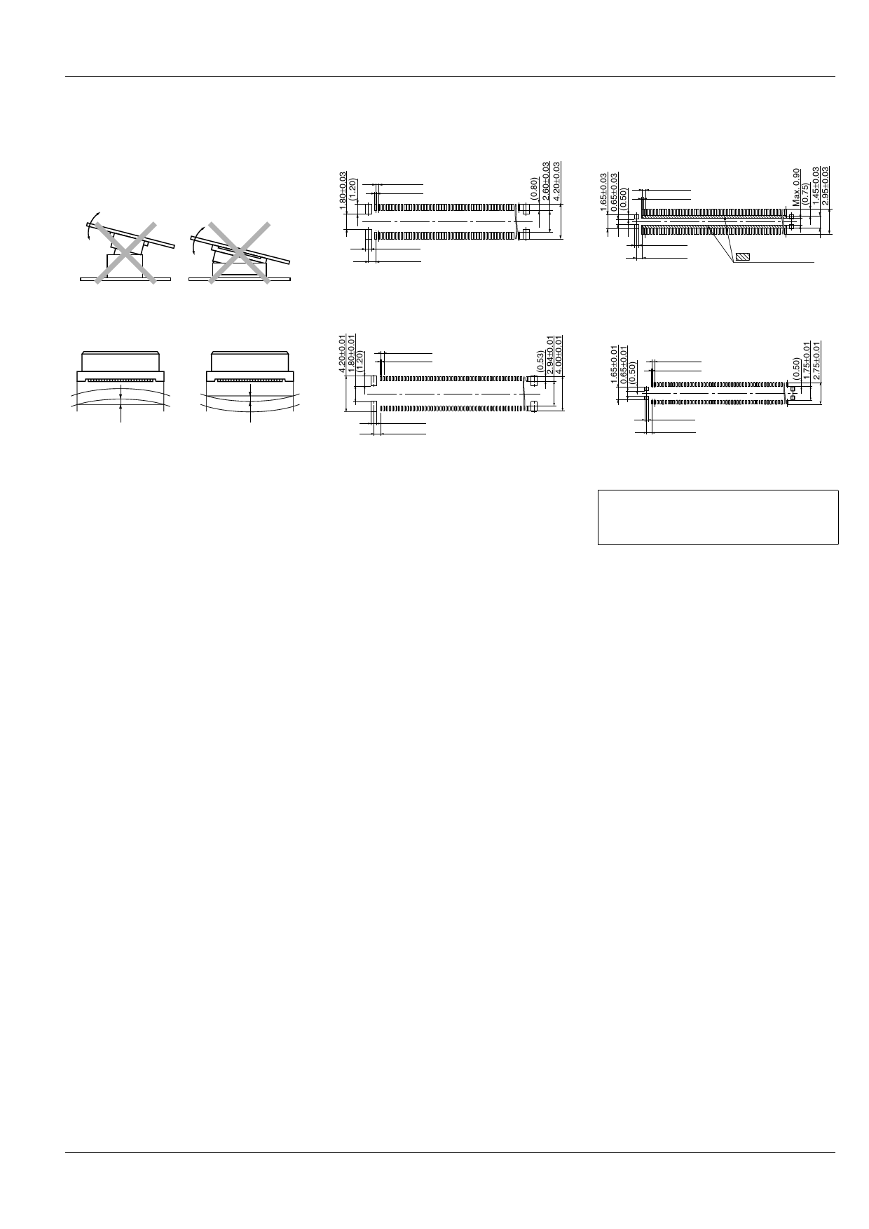
1. As shown below, excess force
during insertion may result in damage
to the connector or removal of the
solder. Also, to prevent connector
damage please confirm the correct
position before mating connectors.
Socket (Mated height: 1.5mm)
Recommended PC board pattern
(TOP VIEW)
0.35±0.03
0.20±0.03
2. Keep the PC board warp no more
than 0.03 mm in relation to the overall
length of the connector
0.70±0.03
0.85±0.03
Recommended metal mask pattern
Metal mask thickness: When 120 µm
(Terminal portion opening area ratio: 60%)
(Metal portion opening area ratio: 100%)
0.35±0.01
0.18±0.01
Max. 0.03 mm
Max. 0.03 mm
3. If extra resistance to shock caused
by dropping is required, we
recommend using P4 Series.
4. Recommended PC board and metal
mask patterns
Connectors are mounted with high pitch
density, intervals of 0.35 mm, 0.4 mm or
0.5 mm.
In order to reduce solder and flux rise,
solder bridges and other issues make
sure the proper levels of solder is used.
The figures to the right are recommended
metal mask patterns. Please use them as
a reference.
0.70±0.01
0.85±0.01
AXT1, 2
Header (Mated height: 1.5mm)
Recommended PC board pattern
(TOP VIEW)
0.35±0.03
0.20±0.03
0.45±0.03
0.70±0.03
: Insulation area
Recommended metal mask pattern
Metal mask thickness: When 120 µm
(Terminal portion opening area ratio: 60%)
(Metal portion opening area ratio: 100%)
0.35±0.01
0.18±0.01
0.45±0.01
0.70±0.01
Please refer to the latest product
specifications when designing your
product.
ACCTB30E 201303-T
Panasonic Corporation Automation Controls Business Division industrial.panasonic.com/ac/e/
Share Link: 