NTE2062 View Datasheet(PDF) - NTE Electronics
Part Name
Description
Manufacturer
NTE2062 Datasheet PDF : 5 Pages
| |||
Operation Description (Cont’d):
Time Setting Input:
Two setting inputs for ’Hours’ and ’Minutes’ are provided. The application of VSS causes the time set-
ting in Table 2 to occur. An internal pull–down resistor each is provided.
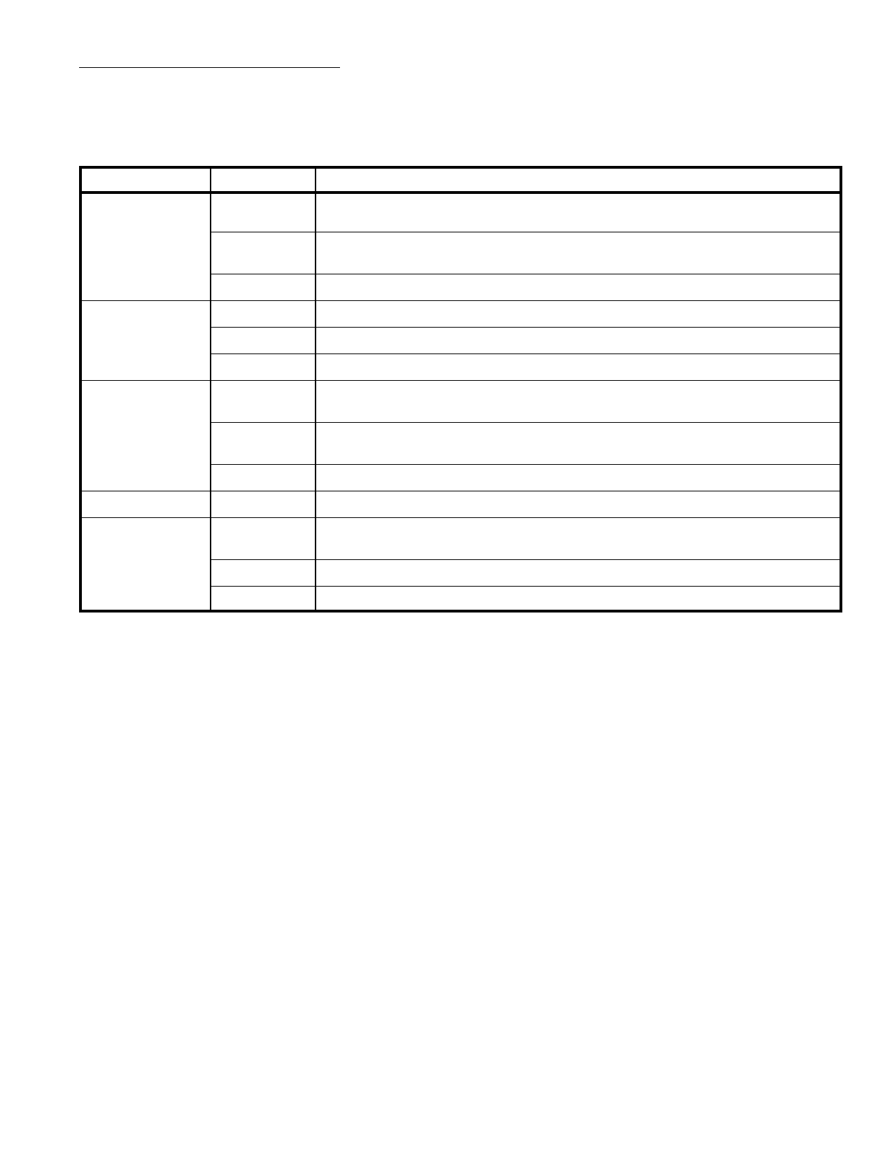
Display Mode
Time
Seconds
(Alarm & Sleep)
Alarm
Sleep
Set Input
Table 2. Setting Contents
Functions
Hour
’Hours’ are incremented +1 immediately and advance at a 2Hz rate 1/4 to 3/4
seconds later.
Minute
’Minutes’ are incremented +1 immediately and advance at a 2Hz rate 1/4 to 3/4
seconds later.
Both
Both operations shown above are preformed.
Hour (Note 2) ’Seconds’ are cleared to [00].
Minute “Hold” mode.
Both (Note 3) ’Hours” and ’Minutes’ are reset to [0:00] (24–Hour basis) or [12:00] (12–Hour basis)
Hour
’Hours’ are incremented +1 immediately and advance at a 2Hz rate 1/4 to 3/4
seconds later.
Minute
’Minutes’ are incremented +1 immediately and advance at a 2Hz rate 1/4 to 3/4
seconds later.
Both
’Hours” and ’Minutes’ are reset to [0:00] (24–Hour basis) or [12:00] (12–Hour basis)
–
Hour
The moment VDD is applied to “Sleep Display”, the sleep counter is set to [:59].
The moment VDD is applied to “Sleep Display” and “Hour Set” simultaneously,
the sleep counter is set to [1:59].
Minute The sleep counter counts down at a 2Hz rate.
Both
The sleep counter counts down at a 2Hz rate.
Note 2. When “Seconds” display is at 50 to 59, “Seconds” are reset to [00] and a carry occurs to incre-
ment “Minutes” +1.
Note 3. Once the reset mode or hold mode is entered, another function is locked until both “Hour Set”
input and “Minute Set” inputs are released.
12/24–Hour Select Input:
Leaving this pin unconnected (VDD) causes the 12–Hour basis to be selected; connecting this pin
to VSS causes the 24–Hour basis to be selected. An internal pull–down resistor is provided.
Power Failure Indicator:
If the power supply voltage drops and is applied again, all the on–segments flash and the power failure
indication mode is entered. The power failure indication mode is released by applying VSS to “Hour
Set” or “Minute Set”.
Alarm Operation and Alarm Output:
When the alarm set time is reached, the alarm signal is delivered. This signal continues to be deliv-
ered for 1 hour 59 minutes unless reset by “Alarm Off” or “Snooze Input”. This signal is provided for
the tone–signal of 900Hz with 50% duty of 2Hz gated. A simple LPF can be used to turn this alarm
signal into DC signal as required.
Snooze Input:
By momentarily connecting this pin to VSS at the alarm on–state, the alarm output is inhibited for 8
to 9 minutes, after which the alarm signal is delivered again. The snooze function can be used repeat-
edly for 1 hour 59 minutes. An internal pull–down resistor is provided. By connecting “Snooze Input”
to VSS at the alarm off–state, the sleep timer counter is reset to [0:00]. (The sleep timer is reset with
one touch).
Share Link: 