AT89C5131A-TISIL(2004) View Datasheet(PDF) - Atmel Corporation
Part Name
Description
Manufacturer
AT89C5131A-TISIL Datasheet PDF : 34 Pages
| |||
AT89C5131A-L
Symbol Parameter
Min
Typ(5)
Max
Unit Test Conditions
VPFDM Power Fail Low Level Threshold
2.2
V
Notes:
Power fail hysteresis VPFDP - VPFDM
0.15
V
1. Operating ICC is measured with all output pins disconnected; XTAL1 driven with TCLCH, TCHCL = 5 ns (see Figure 9.), VIL =
VSS + 0.5V,
VIH = VCC - 0.5V; XTAL2 N.C.; EA = RST = Port 0 = VCC. ICC would be slightly higher if a crystal oscillator used (see Figure
6.).
2. Idle ICC is measured with all output pins disconnected; XTAL1 driven with TCLCH, TCHCL = 5 ns, VIL = VSS + 0.5V, VIH = VCC -
0.5V; XTAL2 N.C; Port 0 = VCC; EA = RST = VSS (see Figure 7).
3. Power-down ICC is measured with all output pins disconnected; EA = VCC, PORT 0 = VCC; XTAL2 NC.; RST = VSS (see Fig-
ure 8.). In addition, the WDT must be inactive and the POF flag must be set.
4. Capacitance loading on Ports 0 and 2 may cause spurious noise pulses to be superimposed on the VOLS of ALE and Ports 1
and 3. The noise is due to external bus capacitance discharging into the Port 0 and Port 2 pins when these pins make 1 to 0
transitions during bus operation. In the worst cases (capacitive loading 100 pF), the noise pulse on the ALE line may exceed
0.45V with maxi VOL peak 0.6V. A Schmitt Trigger use is not necessary.
5. Typicals are based on a limited number of samples and are not guaranteed. The values listed are at room temperature.
6. Under steady state (non-transient) conditions, IOL must be externally limited as follows:
Maximum IOL per port pin: 10 mA
Maximum IOL per 8-bit port:
Port 0: 26 mA
Ports 1, 2 and 3: 15 mA
Maximum total IOL for all output pins: 71 mA
If IOL exceeds the test condition, VOL may exceed the related specification. Pins are not guaranteed to sink current greater
than the listed test conditions.
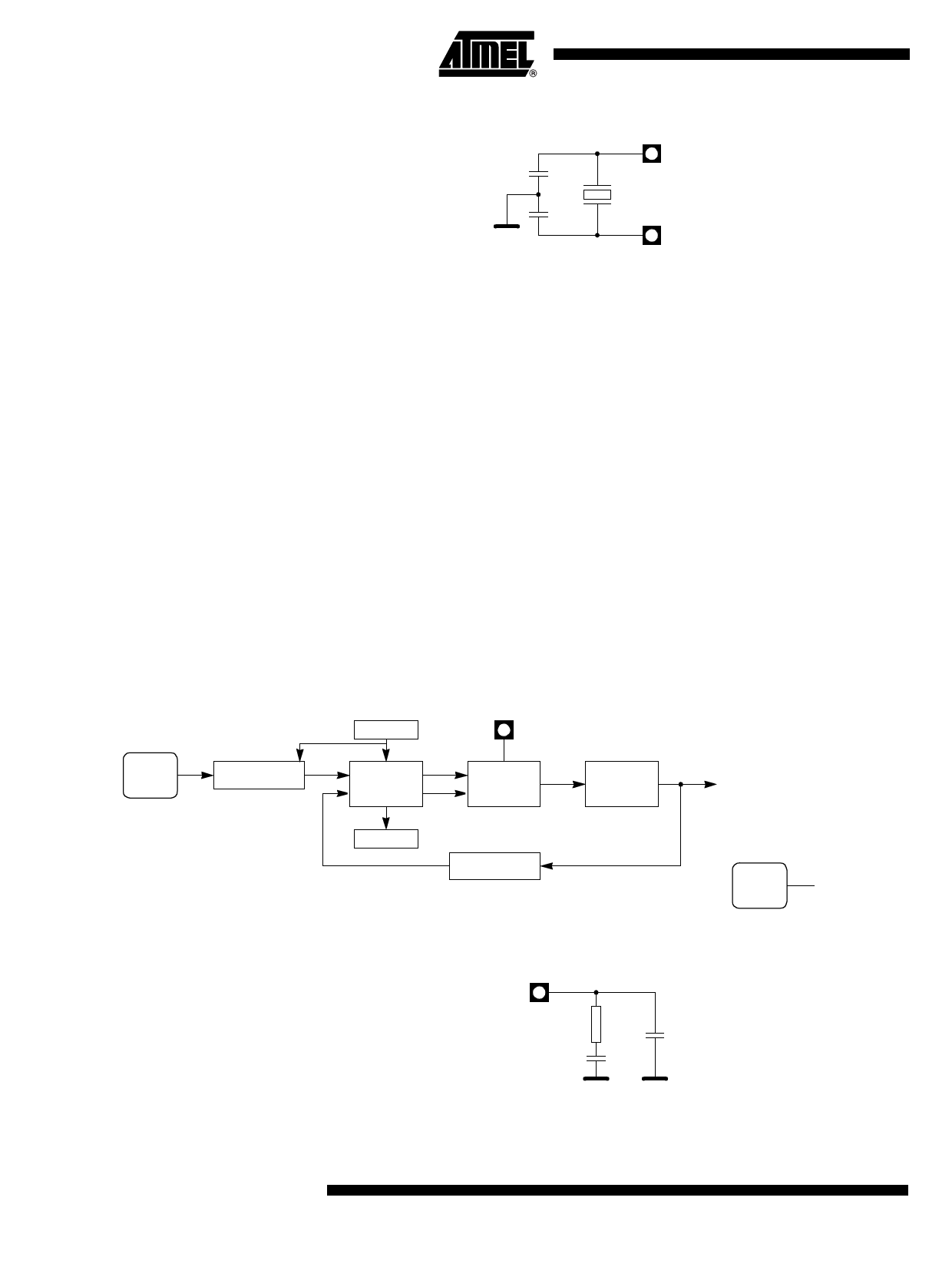
Figure 6. ICC Test Condition, Active Mode
VCC
ICC
VCC
VCC
P0
RST EA
(NC)
CLOCK
SIGNAL
XTAL2
XTAL1
VSS
All other pins are disconnected.
15
4338A–USB–08/04
Share Link: 