AT89C5131A-M(2005) View Datasheet(PDF) - Atmel Corporation
Part Name
Description
Manufacturer
AT89C5131A-M Datasheet PDF : 184 Pages
| |||
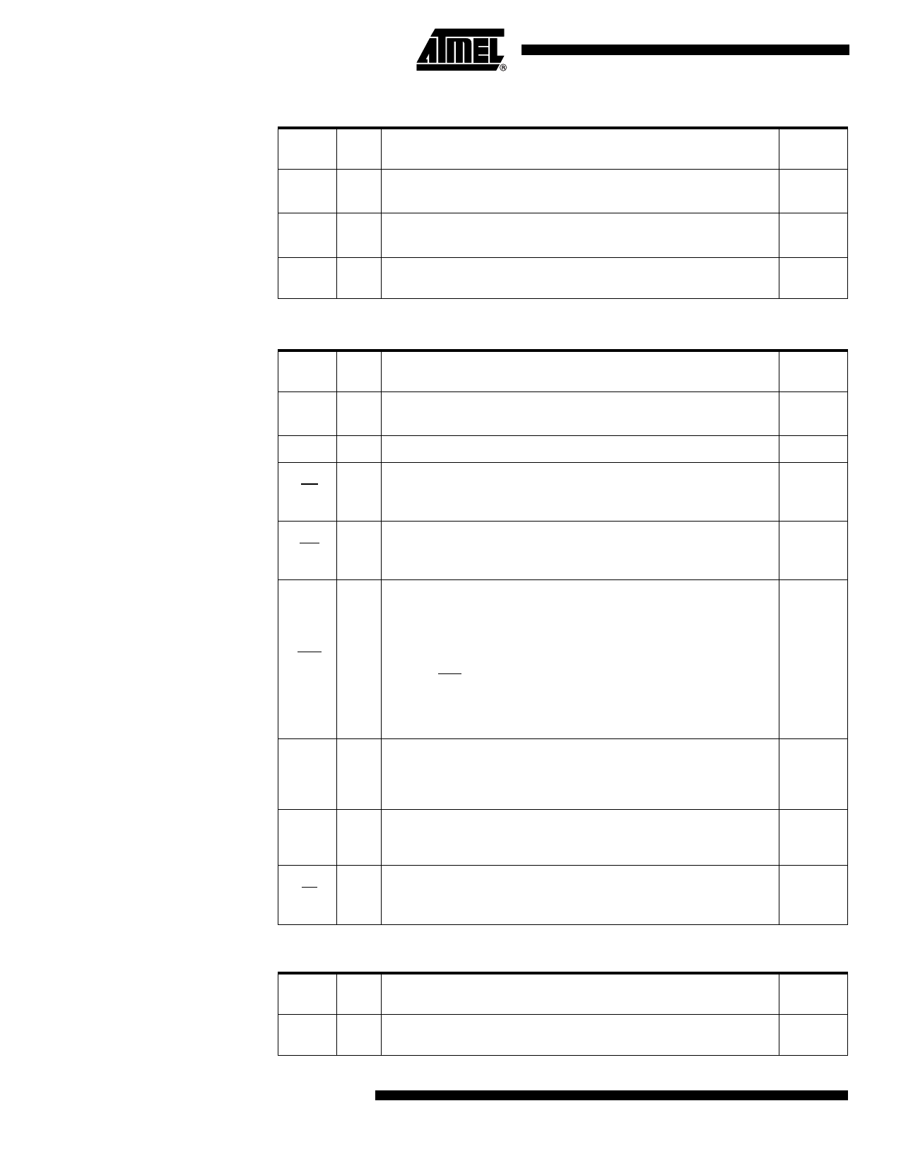
Table 11. System Signal Description
Signal
Name Type Description
Alternate
Function
AD[7:0]
Multiplexed Address/Data LSB for external access
I/O
Data LSB for Slave port access (used for 8-bit and 16-bit modes)
P0[7:0]
A[15:8]
Address Bus MSB for external access
I/O
Data MSB for Slave port access (used for 16-bit mode only)
P2[7:0]
Read Signal
RD
I/O Read signal asserted during external data memory read operation.
Control input for slave port read access cycles.
P3.7
Write Signal
WR
I/O Write signal asserted during external data memory write operation.
Control input for slave write access cycles.
P3.6
Reset Input
Holding this pin low for 64 oscillator periods while the oscillator is running
resets the device. The Port pins are driven to their reset conditions when a
voltage lower than VIL is applied, whether or not the oscillator is running.
RST
O
This pin has an internal pull-up resistor which allows the device to be reset
by connecting a capacitor between this pin and VSS.
-
Asserting RST when the chip is in Idle mode or Power-down mode returns
the chip to normal operation.
This pin is tied to 0 for at least 12 oscillator periods when an internal reset
occurs ( hardware watchdog or power monitor).
Address Latch Enable Output
ALE
O
The falling edge of ALE strobes the address into external latch. This signal
is active only when reading or writing external memory using MOVX
-
instructions.
PSEN
O
Program
Test mode entry signal. This pin must be set to VDD for normal operation.
-
External Access Enable
EA
I This pin must be held low to force the device to fetch code from external
-
program memory starting at address 0000h. It is latched during reset and
cannot be dynamically changed during operation.
Table 12. Power Signal Description
Signal
Name Type Description
Alternate
Function
AVSS
GND
Analog Ground
AVSS is used to supply the on-chip PLL and the USB PAD.
-
AVDD
PWR
Analog Supply Voltage
AVDD is used to supply the on-chip PLL and the USB PAD.
-
VSS
GND
Digital Ground
VSS is used to supply the buffer ring and the digital core.
-
UVSS
GND
USB Digital Ground
UVSS is used to supply the USB pads.
-
USB Pad Power Capacitor
UCAP PWR UCAP must be connect to an external capacitor for USB pad power supply
-
(for typical application see Figure 4 on page 12)
10 AT89C5130A/31A-M
4337C–USB–02/05
Share Link: 