LH28F016LLT-12 View Datasheet(PDF) - Sharp Electronics
Part Name
Description
Manufacturer
LH28F016LLT-12 Datasheet PDF : 29 Pages
| |||
LH28F016LL
16M (1M Г— 16, 2M Г— 8) Flash Memory
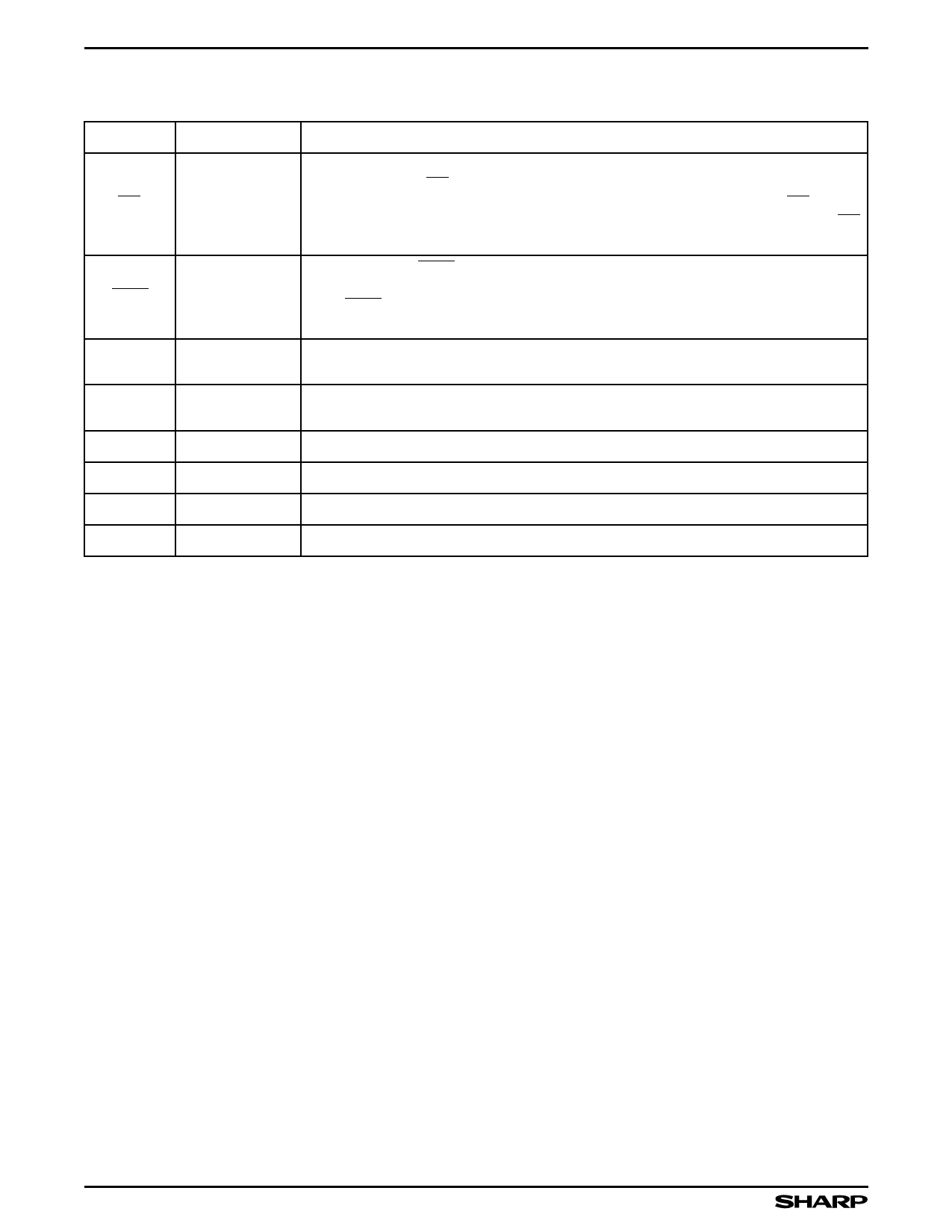
PIN DESCRIPTION (Continued)
SYMBOL
TYPE
WP
INPUT
BYTE INPUT
LX
INPUT
LC
VCC
GND
NC
VSSL
INPUT
SUPPLY
SUPPLY
NAME AND FUNCTION
WRITE PROTECT: Erase blocks can be locked by writing a non-volatile lock-bit for
each block. When WP is low, those locked blocks as reflected by the Block-Lock Status
bits (BSR.6), are protected from inadvertent Data Writes or Erases. When WP is high,
all blocks can be Written or Erased regardless of the state of the lock-bits. The WP
input buffer is disabled when RPВ» transitions low (deep power-down mode).
BYTE ENABLE: BYTE low places device in x8 mode. All data is then input or output
on DQ0 - DQ7, and DQ8 - DQ15 float. Address A0 selects between the high and low
byte. BYTE high places the device in x16 mode, and turns off the A0 input buffer.
Address A1, then becomes the lowest order address.
INPUT FROM OUTSIDE INDUCTOR: Input pin for outside inductor in DC/DC
converter circuit. Connect 1.8 (ВөH) inductor from VCC.
INPUT FROM OUTSIDE CAPACITOR: Input pin for outside capacitor in DC/DC
converter circuit. Ground at 22000 (pF) capacitor.
DEVICE POWER SUPPLY 3.0 V (2.7 V to 3.6 V): Do not leave any power pins floating.
GROUND FOR ALL INTERNAL CIRCUITRY: Do not leave any ground pins floating.
NO CONNECT: No internal connection to die, lead may be driven or left floating.
GROUND
4
Share Link: 