HM8350A View Datasheet(PDF) - Unspecified
Part Name
Description
Manufacturer
HM8350A Datasheet PDF : 3 Pages
| |||
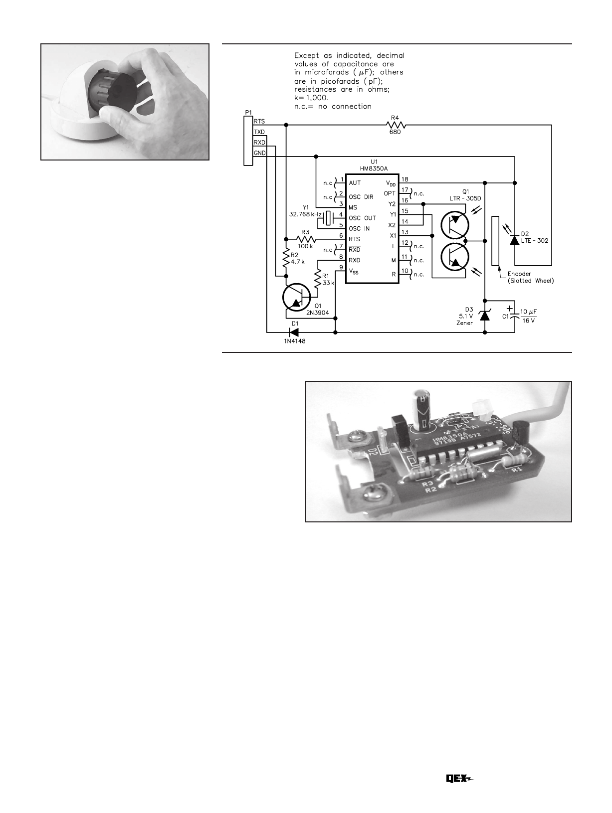
Fig 7—Schematic diagram of the
mouse-chip circuit.
Fig 6—Completed tuning knob assembly.
a construction site and machined un-
til presentable, then painted.
A Serial-Mouse Circuit
Refer to Fig 7, a schematic diagram.
The mouse chip gets its power from the
computer’s EIA-232 TxD line, since
that line is not doing anything else in
this case. Only the RxD line carries
data. D1 protects against reverse po-
larity in case the TxD line goes to the
positive rail. D3 sets the supply volt-
age to the mouse chip at about 5 V dc.
The power for the LED comes from the
RTS line, which also does not toggle.
Phototransistors Q1 are tied di-
rectly to the chip. Tuning-fork resona-
tor Y1 provides a clock for the chip.
Transistor Q2 level-shifts the R×D
output to EIA-232 levels. Output
comes at 1200 baud and standard
mouse driver software running on a
PC may be used to detect knob rota-
tion commands from either the X or Y
detector. Pins L, M and R would nor-
mally be hooked to the three SPST
switches on a mouse or trackball.
Those could have been used to change
the tuning rate or to implement some
other function, but they were left un-
connected here.
Fig 8 is a close-up of the circuit as-
sembly. The encoder disk fits between
the LED and the phototransistors
when assembled. The LED is an LTE-
302; the phototransistor pair is a
single, three-pin unit: LTR-305D.2
Note: Modern PC operating systems
tend to interrogate devices connected
to serial ports at boot time. Since my
knob circuit looks just like a mouse to
the PC, it is wise to connect a serial PC
mouse or trackball to a lower-num-
bered COM port than that of the knob.
Otherwise, the PC will install the knob
as the pointing device and you will find
the icon traveling diagonally across
the screen as you rotate the knob; your
mouse will be tuning your radio!
The Knob Itself
In these days of push-button, menu-
Fig 8—A
close-up view
of the PC
assembly.
driven machinery, decent tuning
knobs are becoming difficult to obtain
“off the shelf.” On the other hand,
regular milling equipment makes it
easy to make a custom knob from
readily available rod stock.
Armed with some three-inch black
Delrin stock3 and a ball-end milling tool,
I was able to produce the massive sym-
metrical tuning knob shown in Fig 7. I
used Delrin because it is an easy-to-
machine plastic that is already black in
color. Aluminum may be used and sub-
sequently anodized if you worry about
marring the Delrin under heavy use.
The ball-end milling tool made it easy to
put a finger hole into the front surface of
the knob and to make flutes that taper
along the knob’s length.
Zack Lau, W1VT, has more to say
about making knobs. Watch for the
topic in an upcoming RF column.
Notes
1Hualon Microelectronics (HMC), www.
hualon.com.tw.
2LiteOn, www.liteon.com. These particular
parts may no longer be available, but
equivalents are. Scrounge them from dead
mice!
3Delrin rod stock is available from McMaster-
Carr Supply Co, www.mcmaster.com.
""
Mar/Apr 2002 3
Share Link: 