HUL7251 View Datasheet(PDF) - Panasonic Corporation
Part Name
Description
Manufacturer
HUL7251 Datasheet PDF : 3 Pages
| |||
Hologram Unit
HUL7251
Hologram Unit
For optical information processing
Features
/ Thin smaller package size achieved through
,,, e. micro-mirror integration
e ,,t,ag (3.3 × 6.8 × 4.3 mm)
s Fast response (fC = 35 MHz)
c cle Focus error signal detection : SSD method
n , , d cy Tracking error signal detection
a ,,,,,e, life : 3 beam method
, ct Low-power semiconductor laser included
n u P,rodu Applications
te tin ur . CD-ROMdrives
g fo pe tion (supports 20- to 24-time speed CD-ROM drives)
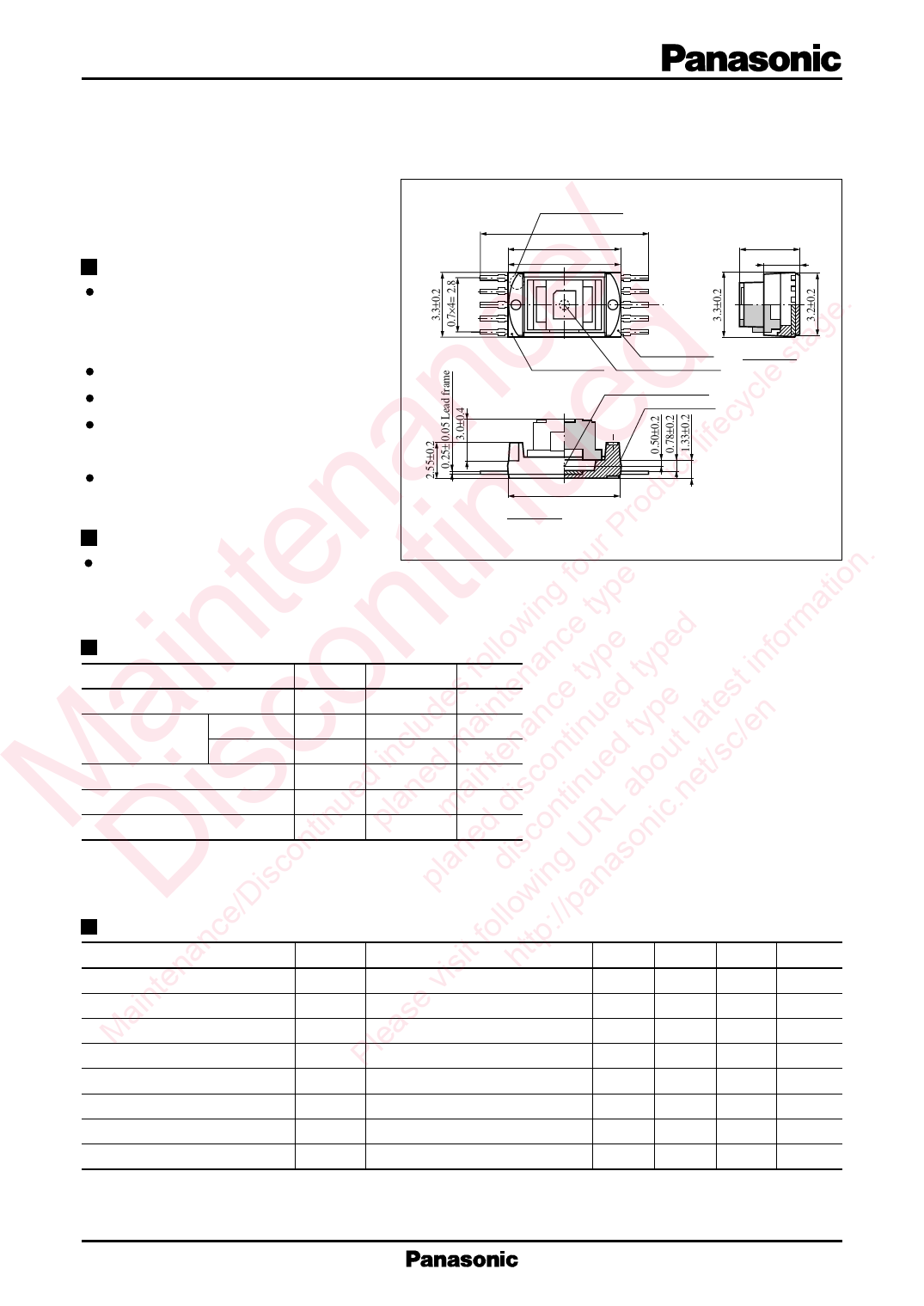
Index mark for No.1
pin on reverse side
Unit : mm
9.8
6.8±0.2
ø6.8
+0
–0.05
4.33±0.4
2.55±0.2
1
10
2
9
3
4
O
8X
7
5
6
Y
Reference plane
Reference plane Apparent emitting point
SEC. X-O-Y
Apparent emitting point
Reference plane
6.7±0.2
SEC. X-O-Y
(Note): 1.Standard corner R=0.20 max.
2.Thickness of plate:Ni 1µm min.+Au 0.1µm min.
3.Thickness of hologram=2.0mm, n=1.519
in n llowinnce type ped forma Absolute Maximum Ratings (Ta = 25˚C)
fo na ty ty in Parameter
Symbol Ratings Unit
a o des inte ce ed e st Laser beam output*1
PO
0.3
mW
clu ma nan tinu typ late n Laser
t /e Reverse voltage
VR(LD)
2
V
c in d te n d c Monitor
VR(mon)
6
V
d e in co ue ou t/s Supply voltage
VR
6
V
M is tinue lan ma dis tin ab .ne Operating ambient temperature Topr – 10 to +60 ˚C
p d on RL ic Storage temperature
Tstg – 40 to +85 ˚C
on ne isc U on *1 Light emitting output through objective lens
Dce/Disc pla dllowin:g//panas Electro-Optical Characteristics (Ta = 25˚C)
an it fo ttp Parameter
n is h Laser beam output
inte e v Operating current
a as Operating voltage
M Ple Oscillating wavelength
Symbol
PO
IOP
VOP
λL
Conditions
CW
CW VRF = 570mV, VCC = 5V
CW VRF = 570mV, VCC = 5V
CW VRF = 570mV, VCC = 5V
min typ max Unit
0.18 0.25 mW
25
35
45
mA
1.9 2.4
V
775 795 815 nm
Focus error signal amplitude
VFE
CW VRF = 570mV, VCC = 5V
340
480
620
mV
Tracking error signal amplitude
VTE
CW VRF = 570mV, VCC = 5V
150
300
450
mV
Focus error signal pull-in range
DFE
CW VRF = 570mV, VCC = 5V
9
12
16
µm
Frequency characteristics (–3 dB) fC
30
35
MHz
*1 Light emitting output through objective lens
1
Share Link: 