LA4601N View Datasheet(PDF) - SANYO -> Panasonic
Part Name
Description
Manufacturer
LA4601N Datasheet PDF : 7 Pages
| |||
Pin Descriptions
1. Standby switching function (7)
LA4601N
Power is switched ON and OFF by controlling the High and Low states at pin
7, respectively (standby). To switch power ON, apply 1.5V or more, or
800µA to pin 7.
Current supplied to pin 7 ≈
Applied voltage Applied voltage - VBE (approx. 0.7V)
+
2kΩ
2kΩ
• When directly connecting a microcontroller with this pin, add a resistor in
series to optimize the current for the microcontroller.
2. Input pins (8,10)
Voltage at the input pins is approx. 2 VBE (1.4V).
Input impedance is approx. 30kΩ.
• The recommended value for the input capacitor is 0.22µF, but this can be varied in order to adjust the starting time (ts).
(The starting time is the time required from applying voltage to the standby pin until sound output is obtained.)
Input capacitator 1.0µF 2.0 µF
Starting time (ts) 0.2s 0.3s
3.3 µF
0.5s
4.7 µF
0.65s
10 µF
1.5s
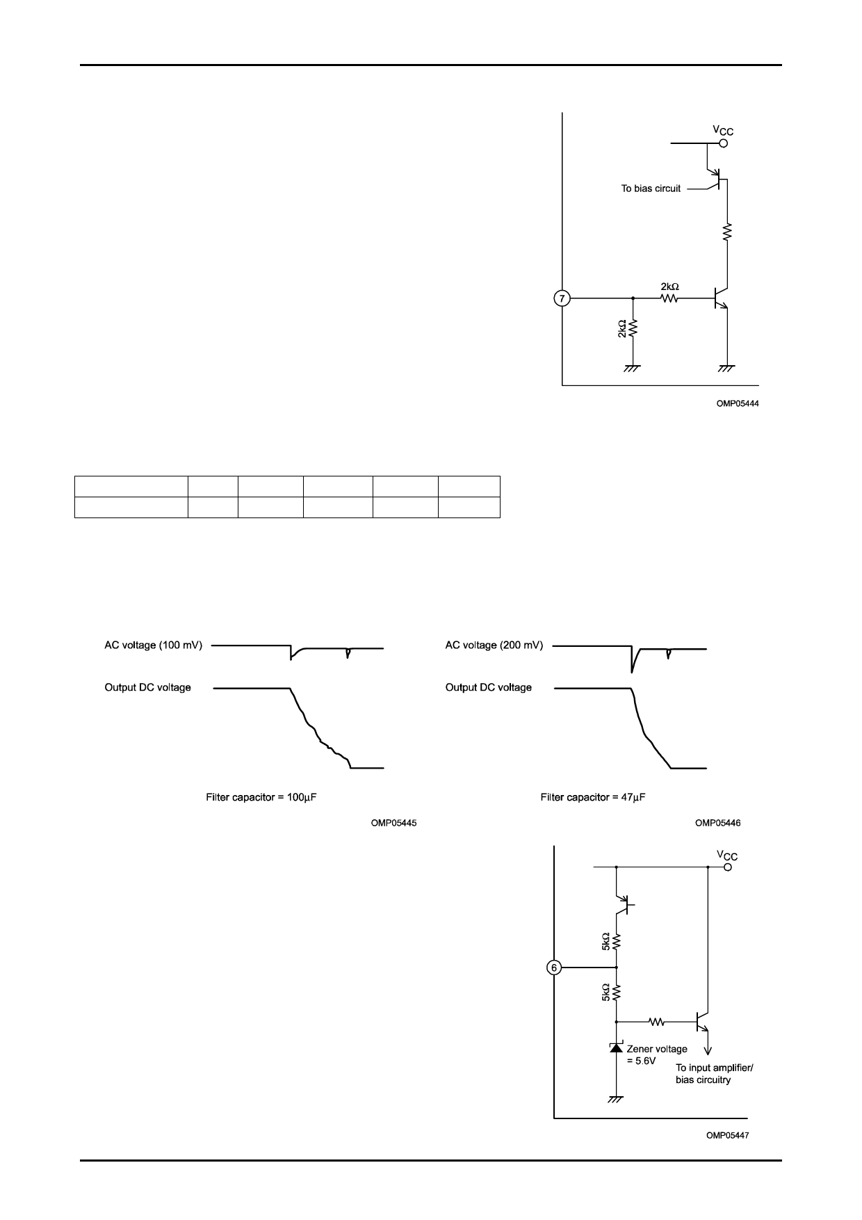
3. Filter (decoupling) pin (5)
Pin voltage is approx. 1/2 VCC.
The recommended value for the filter capacitor is 100µF.
When capacitance is lower, pop noise when setting the standby pin to Low (power OFF) will increase.
4. P.P (pop noise) pin (6)
VCC - VCE (approx. 0.3V) - 5.6V
Voltage at pin 6 ≈ + 5.6V
2kΩ
• The recommended value for the P.P capacitor is 4.7µF.
When capacitance is lower than 2.2µF, pop noise when setting the standby
pin to Low (power OFF) will increase.
When capacitance is higher than 10µF, the sound will not be cut off when
setting the standby pin to Low (power OFF).
No.8168-4/7
Share Link: 