UTC2003 View Datasheet(PDF) - Unspecified
Part Name
Description
Manufacturer
UTC2003 Datasheet PDF : 8 Pages
| |||
UTC2003
LINEAR INTEGRATED CIRCUIT
SVR
(dB)
0
-20
-40
Fig. 10 Supply voltage
rejection vs.frequency
Vs=14.4V
Vripple=0.5V
Gv=40dB
f=1kHz
Rg=10kΩ
R2=22Ω
-60
R2=1Ω
-80
10
102
103
104
105
frequency(Hz)
Fig. 13 Maximum Power
dissipation and supply
voltage(sine wave operation)
Ptot
(W )
20
15
RL=1.6Ω
10
RL=2Ω
RL=3.2Ω
5
RL=4Ω
0
0
5
10
15
20 Vs(V)
Fig. 11 Power dissipation
and efficiency vs. output
power(Rl=4Ω)
Ptot
(W)
8
η
Vs=14.4V
6
Gv=40dB
f=1kHz
4
Ptot
2
Fig. 12 Power dissipation
and efficiency vs. output
power(Rl=2Ω)
η
Ptot
η
(%) (W)
(%)
80
8
Vs=14.4V
80
Gv=40dB
f=1kHz
60
6
60
40
4
40
20
2
20
0
0
0
2
4
6
8
Po(W)
Ptot
(W )
20
Fig. 14 Maximum allowable
dissipation and ambient
temperature
infinite heatsink
15
10
℃ 10 /W
5
℃ 30 /W
0
0
50
100
150
℃ 200
Tamb( )
0
0
100
Cx
(nF)
0
2
4
6
8
Po(W)
Fig. 15 Typical values of
capacitor(Cx) for different
values of frequency
response
B=10kHz
B=15kHz
10
B=20kHz
R2=2.2Ω
1
36
40
44
48 Gv(dB)
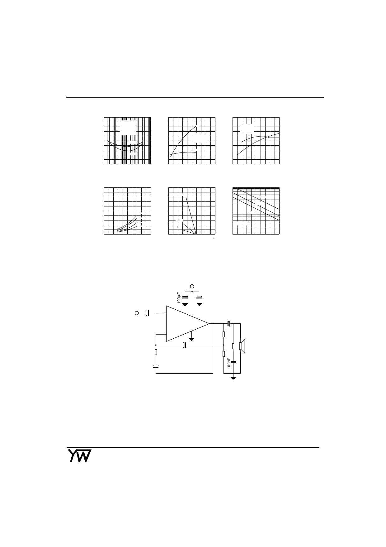
APPLICATION INFORMATION
+Vs
C3
100nF
Vi
C1
1µF
1
5
C4
UTC2003
4
1000µF
2
3
R1
220Ω R3
Rx
C2
39Ω
470µF
1Ω
RL
R2
Cx
2.2Ω
39nF
Rx=20*R2
Cx=1/(2πB*R1)
Fig 16 Typical application circuit
YOUWANG ELECTRONICS CO.LTD
5
Share Link: 