STK402-040 View Datasheet(PDF) - SANYO -> Panasonic
Part Name
Description
Manufacturer
STK402-040 Datasheet PDF : 4 Pages
| |||
STK402-040
Series Organization
These products are organized as a series based on their output capacity.
Type No.
Item
STK402-020 STK402-030 STK402-040 STK402-050 STK402-070 STK402-090 STK402-100 STK402-120
Output 1 (10%/1 kHz)
20 W + 20 W 30 W + 30 W 40 W + 40 W 45 W +45 W 60 W + 60 W 80 W + 80 W 100 W + 100 W 120 W + 120 W
Output 2 (0.4%/20 Hz to 20 kHz) 15 W + 15 W 20 W + 20 W 25 W + 25 W 30 W + 30 W 40 W + 40 W 50 W + 50 W 60 W + 60 W 80 W + 80 W
Maximum supply voltage
(No signal)
±30 V
±34 V
±38 V
±40 V
±50 V
±54 V
±57 V
±65 V
Maximum supply voltage
(6 Ω)
±28 V
±32 V
±36 V
±38 V
±44 V
±47 V
±50 V
±57 V
Recommended supply voltage
(6 Ω)
±19 V
±22 V
±25 V
±26.5 V
±30 V
±32 V
±35 V
±39 V
Package
46.6 mm × 25.5 mm × 8.5 mm
59.2 mm × 31.0 mm × 8.5 mm
Specifications
Maximum Ratings at Ta = 25°C
Parameter
Maximum supply voltage (No signal)
Maximum supply voltage
Thermal resistance
Junction temperature
Operating IC substrate temperature
Storage temperature
Allowable load shorted time *2
Symbol
Conditions
VCC max(0)
VCC max(1)
θj-c
RL = 6 Ω
Per power transistor
Tj max
Tc max
Both the Tj max and the Tc max conditions must be met.
Tstg
ts
VCC = ±25.0 V, RL = 6 Ω, f = 50 Hz, PO = 25 W
Ratings
±38
±36
3.6
150
125
–30 to +125
0.3
Unit
V
V
°C/W
°C
°C
°C
s
Operating Characteristics at Tc = 25°C, RL = 6 Ω (noninductive load), Rg = 600 Ω, VG = 30 dB
Parameter
Output power
(continuous output)
Total harmonic distortion
Frequency characteristics
Input impedance
Output noise voltage *3
Quiescent current
Neutral voltage
Symbol
PO (1)
PO (2)
THD (1)
THD (2)
fL, fH
ri
VNO
ICCO
VN
VCC (V) f (Hz)
±25.0 20 to 20 k
±25.0
1k
±25.0 20 to 20 k
±25.0
1k
±25.0
±25.0
1k
±30.0
±30.0
±30.0
Conditions*1
PO (W) THD (%)
0.4
10
1.0
5.0
1.0
1.0
+0 –3 dB
Rg = 2.2 kΩ
min
23
Ratings
typ
25
40
0.01
20 to 50 k
55
20
50
–70
0
Unit
max
W
0.4
%
Hz
kΩ
1.2 mVrms
80 mA
+70 mV
Notes: 1. Unless otherwise noted, use a constant-voltage supply for the power supply used during inspection.
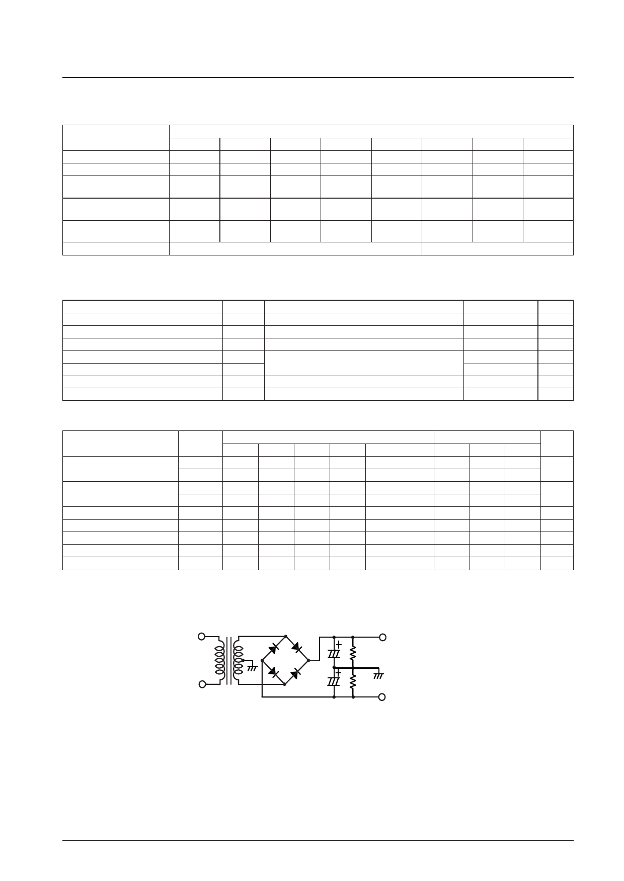
2. Use the transformer power supply circuit stipulated in the figure below for allowable load shorted time measurement and output noise voltage
measurement.
DBA40C
4700 µF
500 Ω
+VCC
500 Ω
4700 µF
--VCC
Stipulated Transformer Power Supply (RP-25 equivalent)
3. The output noise voltage values shown are peak values read with a VTVM. However, an AC stabilized (50 Hz) power supply should be used to
minimize the influence of AC primary side flicker noise on the reading.
No. 7062-2/4
Share Link: 