BWR-5/3-3.3/4.25-D12A View Datasheet(PDF) - Murata Power Solutions
Part Name
Description
Manufacturer
BWR-5/3-3.3/4.25-D12A
Murata Power Solutions

BWR-5/3-3.3/4.25-D12A Datasheet PDF : 6 Pages
| |||
Absolute Maximum Ratings
Input Voltage:
Continuous:
D12A Models
D24A Models
D48A Models
Transient (100msec): D12A Models
D24A Models
D48A Models
23 Volts
42 Volts
81 Volts
25 Volts
50 Volts
100 Volts
Input Reverse-Polarity Protection
D12A Models
D24A Models
D48A Models
Input Current must be limited. 1 minute
duration. Fusing recommended.
6 Amps
4 Amps
2 Amps
Output Current ➁
Current limited. Devices can withstand
an indefinite output short circuit.
On/Off Control (Pins 3 & 4) Max. Voltages
Referenced to –Input (pin 2)
D12A, D24A & D48A Models
+VIN
"N" Models
±19V
Storage Temperature
–40 to +120°C
Lead Temperature (Soldering, 10 sec.) +300°C
These are stress ratings. Exposure of devices to any of these conditions may adversely
affect long-term reliability. Proper operation under conditions other than those listed in
the Performance/Functional Specifications Table is not implied, nor recommended.
TECHNICAL NOTES
Trimming Output Voltages
These BWR converters have a trim capability (pins 3 & 4) that allow users
to independently adjust the output voltages ±5%. Adjustments to the output
voltages can be accomplished via a trim pot, Figure 2, or a single fixed resistor
as shown in Figures 3 and 4. A single fixed resistor can increase or decrease
the output voltage depending on its connection. Fixed resistors should have
absolute TCR's less than 100ppm/°C to minimize sensitivity to changes in
temperature.
A single resistor connected from the 5V Trim pin (pin 7) to the +5V Output
(pin 5), see Figure 3, will decrease the +5V output voltage. A resistor con-
nected from the +5V Trim (pin 7) to the +5V Return (pin 6) will increase the
+5V output voltage. See Figure 4.
Similarly, the 3.3V output can be adjusted using a single resistor connected
from the +3.3V Trim (pin 10) to the +3.3V Output (pin 9) or to the +3.3V Return
(pin 8). See Figures 3 and 4.
1
+INPUT
2
–INPUT
3 +5V
ON/OFF
CONTROL
4 +3.3V
ON/OFF
CONTROL
5
+5V OUTPUT
7
+5V TRIM
6
+5V RETURN
8
+3.3V RETURN
10
+3.3V TRIM
9
+3.3V OUTPUT
20kΩ
5-22
TURNS
+5V
LOAD
20kΩ
5-22
TURNS
+3.3V
LOAD
Figure 2. Trim Connections Using A Trim Pot
www.murata-ps.com/support
Dual Output BWR Models
Mixed Voltage, 5V and 3.3V, Independent Dual Output
30 Watt DC/DC Converters
1
+INPUT
2
–INPUT
3 +5V
ON/OFF
CONTROL
4 +3.3V
ON/OFF
CONTROL
5
+5V OUTPUT
6
+5V RETURN
+5V LOAD
+5V TRIM
+3.3V RETURN
7
5V RTRIM DOWN
8
9
+3.3V OUTPUT
+3.3V LOAD
10
+3.3V TRIM
3.3V RTRIM DOWN
2.49(VO – 2.52)
2.49(VO – 1.27)
5V RTDOWN (kΩ) =
5 – VO
–15 3.3V RTDOWN (kΩ) = 3.3 – VO
–14.3
Figure 3. Trim Connections To Decrease Output Voltages Using Fixed Resistors
1
+INPUT
2
–INPUT
3 +5V
ON/OFF
CONTROL
4 +3.3V
ON/OFF
CONTROL
5
+5V OUTPUT
6
+5V RETURN
+5V LOAD
7
+5V TRIM
8
+3.3V RETURN
5V RTRIM UP
9
+3.3V OUTPUT
+3.3V LOAD
10
+3.3V TRIM
3.3V RTRIM UP
6.27
5V RT UP (kΩ) =
–15
VO – 5
3.16
3.3V RTUP (kΩ) =
–14.3
VO – 3.3
Figure 4. Trim Connections To Increase Output Voltages Using Fixed Resistors
Note: Resistor values are in kΩ. Accuracy of adjustment is subject to
tolerances of resistors and factory-adjusted output accuracy.
VO = desired output voltage.
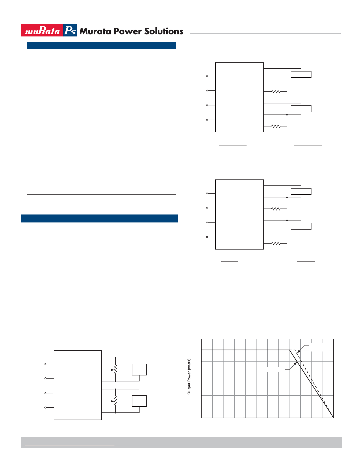
Typical Performance Curves
Output Power vs. Ambient Temperature
(VIN nominal, natural convection air flow.)
35
30
D24A, D48A
MODELS
25
D12A MODELS
20
15
10
5
0
–40 –10 0
10 20 30 40 50 60 70 80
Ambient Temperature (°C)
90 100
MDC_BWR30.B05 Page 4 of 6
Share Link: