F71882FG View Datasheet(PDF) - Feature Integration Technology Inc.
Part Name
Description
Manufacturer
F71882FG Datasheet PDF : 130 Pages
| |||
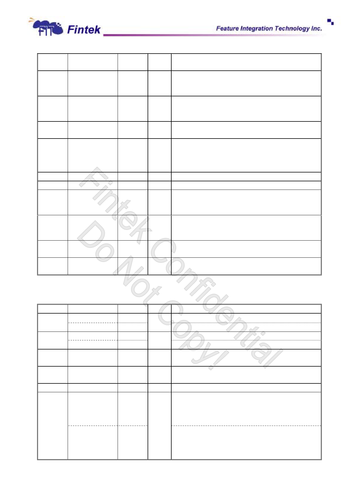
F71882
9
DRVA#
OD24
VCC Drive Select A. When set to 0, this pin enables disk
drive A. This is an open drain output.
10
WDATA#
OD24
VCC Write data. This logic low open drain writes
pre-compensation serial data to the selected FDD. An
open drain output.
11
DIR#
OD24
VCC Direction of the head step motor. An open drain output.
Logic 1 = outward motion
Logic 0 = inward motion
12
STEP#
OD24
VCC Step output pulses. This active low open drain output
produces a pulse to move the head to another track.
13
HDSEL#
OD24
VCC Head select. This open drain output determines which
disk drive head is active.
Logic 1 = side 0
Logic 0 = side 1
14
WGATE#
OD24
VCC Write enable. An open drain output.
15
RDATA#
INts5v
VCC The read data input signal from the FDD.
16
TRK0#
INts5v
VCC Track 0. This Schmitt-triggered input from the disk
drive is active low when the head is positioned over
the outermost track.
17
INDEX#
INts5v
VCC This Schmitt-triggered input from the disk drive is
active low when the head is positioned over the
beginning of a track marked by an index hole.
18
WPT#
INts5v
VCC Write protected. This active low Schmitt input from the
disk drive indicates that the diskette is write-protected.
19
DSKCHG#
INts5v
VCC Diskette change. This signal is active low at power on
and whenever the diskette is removed.
6.4 UART and SIR
Pin No.
27
28
118
Pin Name
IRTX
GPIO42
IRRX
GPIO43
DCD1#
119
RI1#
120
CTS1#
121
DTR1#
FAN60_100
Type
O12
I/OOD12t
INts
I/OOD12t
INt5v
INt5v
INt5v
O8-u47,5v
INt5v
PWR
VCC
VSB
VCC
VCC
VCC
VCC
Description
Infrared Transmitter Output.
General Purpose IO
Infrared Receiver input.
General Purpose IO.
Data Carrier Detect. An active low signal indicates the
modem or data set has detected a data carrier.
Ring Indicator. An active low signal indicates that a ring
signal is being received from the modem or data set.
Clear To Send is the modem control input.
UART 1 Data Terminal Ready. An active low signal
informs the modem or data set that controller is ready to
communicate. Internal 47k ohms pulled high and disable
after power on strapping.
Power on strapping pin:
1(Default): (Internal pull high)
Power on fan speed default duty is 60%.(PWM)
0: (External pull down)
-7-
May, 2008
V0.28P
Share Link: 