DCR1002SF14 View Datasheet(PDF) - Dynex Semiconductor
Part Name
Description
Manufacturer
DCR1002SF14 Datasheet PDF : 9 Pages
| |||
DCR1002SF
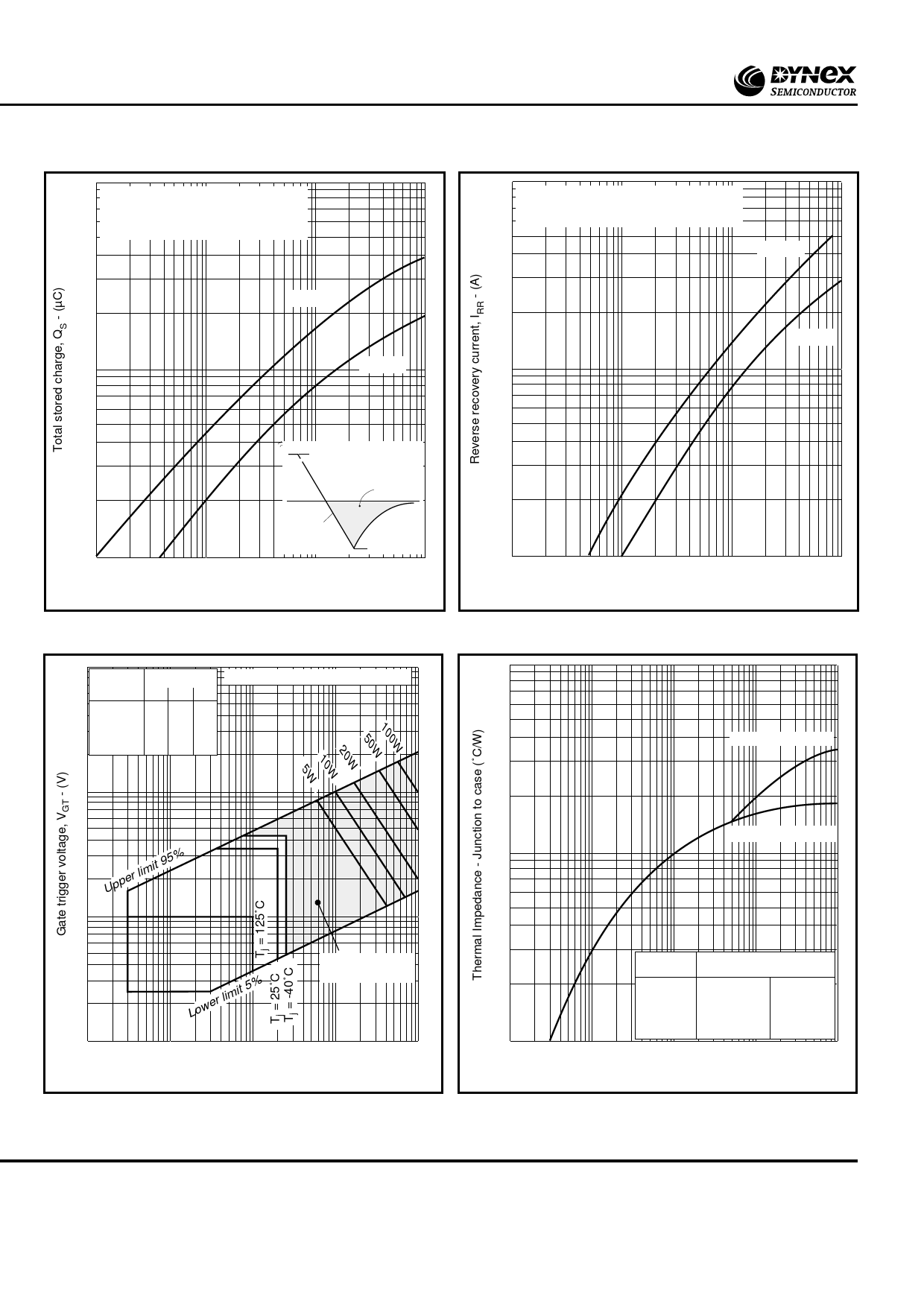
10000
Conditions: IT = 1000A, VR = –100V,
Tj = 125˚C
QS is total integral stored charge
1000
Max QS
Min QS
10000
Conditions: IT = 1000A, VR = –100V,
Tj = 125˚C
Max IRR
1000
Min IRR
IT
QS
100
0.1
dI/dt
IRR
1.0
10
100
Rate of decay of on-state current, dI/dt - (A/µs)
Fig.4 Stored charge
100
Pulse width Frequency Hz
µs
50 100 400
100 150 150 150
200 150 150 125
500 150 150 100
1ms 150 50 25
10ms 20 - -
Table gives pulse power PGM in Watts
10
Upper limit 95%
1
VGD
0.1
0.001
Lower limit 5%
Region of certain
triggering
0.01
0.1
1
10
Gate trigger current, IGT - (A)
Fig.6 Gate characteristics
100
0.1
1.0
10
100
Rate of decay of on-state current, dI/dt - (A/µs)
Fig.5 Reverse recovery current
0.1
Anode side cooled
Double side cooled
0.01
0.001
0.001
0.01
Conduction
Effective thermal resistance
Junction to case ˚C/W
d.c.
Halfwave
3 phase 120˚
6 phase 60˚
Double side
0.018
0.021
0.022
0.025
Anode side
0.036
0.038
0.040
0.043
0.1
1.0
10
Time - (s)
Fig.6 Transient thermal impedance - junction to case
6/9
www.dynexsemi.com
Share Link: 