AP494 View Datasheet(PDF) - Anachip Corporation
Part Name
Description
Manufacturer
AP494 Datasheet PDF : 9 Pages
| |||
Voltage Mode PWM Controller
AP494
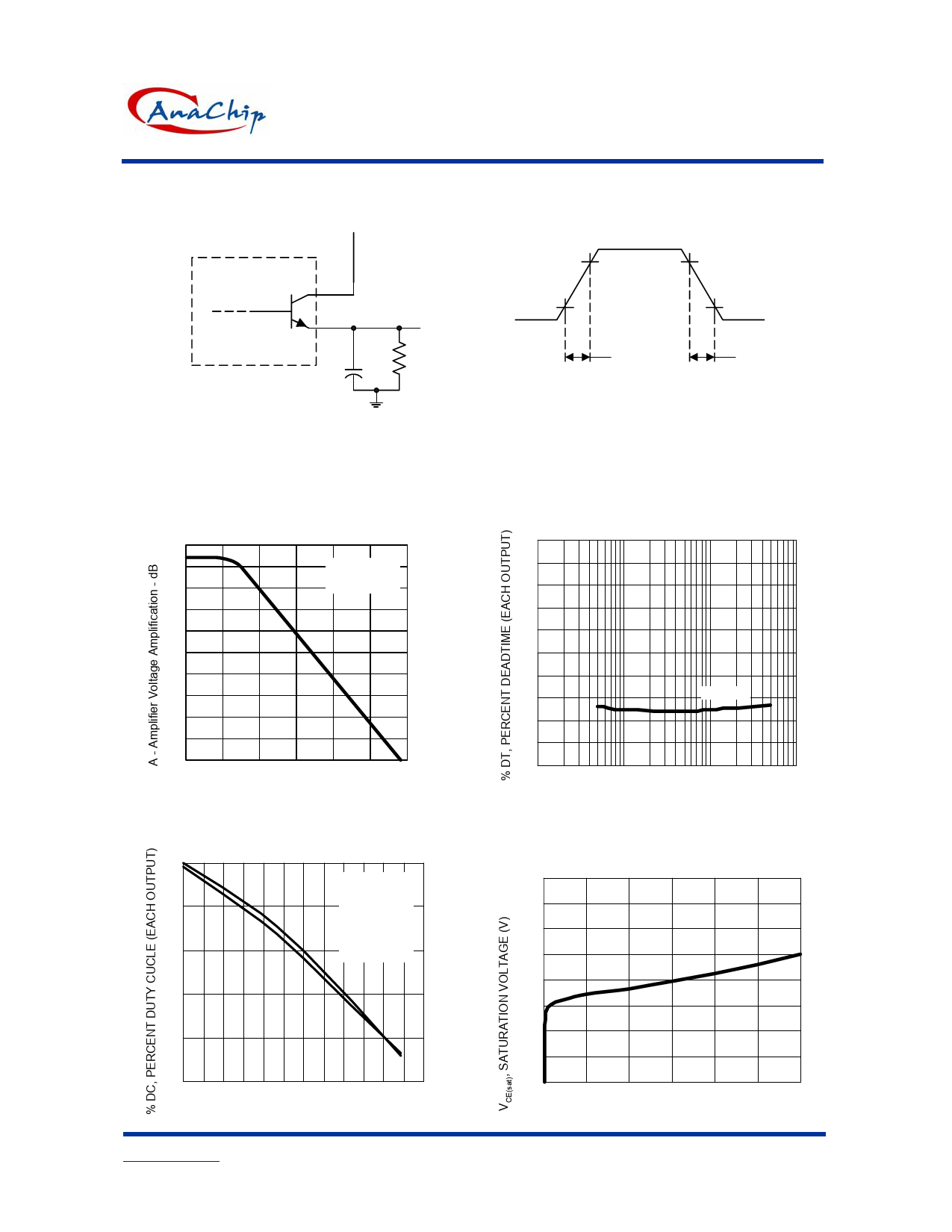
Figure 5. EMITTER-FOLLOWER CONFIGURATION
15 V
Each Output
Circuit
CL=15 pF
(See Note A)
Output
68Ω
2W
TEST CIRCUIT
NOTE A. CL includes probe and jig capacitance.
Figure 6.
AMPLIFIER VOLTAGE AMPLIFICATION
vs FREQUENCY
100
90
VCC∆ = 15V
Vo = 3V
80
TA = 25oC
70
60
50
40
30
20
10
0
1 10 100 1K 10K 100K 1M
f - Frequency - Hz
Figure 8.
Percent Duty versus Deadtime Control Voltage
50
VCC=15V
40
VOC=Vref
1.CT=0.01uF
RT=10kΩ
2.CT=0.001uF
30
RT=30kΩ
20
10
0
0
1
2
3
VDT, DEADTIME CONTROL VOLTAGE (IV)
Anachip Corp.
www.anachip.com.tw
6/9
90%
10%
tr
90%
10%
tf
OUTPUT VOLTAGE WAVEFORM
Figure 7.
Percent Deadtime versus Oscillator Frequency
20
18
16
14
12
10
8
6
0.001µF
4
2
0
0.1
1
10
100
fOSC, OSCILLATOR FREQUENCY (Hz) (K)
Figure 9.
Emitter-Follower Configuration Output
Saturation Voltage versus Emitter Current
1.9
1.8
1.7
1.6
1.5
1.4
1.3
1.2
1.1
0
100
200
300
IE, EMITTER CURRENT (mA)
Rev.1.0 Oct 11, 2004
Share Link: 