MP54C View Datasheet(PDF) - Semtech Corporation
Part Name
Description
Manufacturer
MP54C Datasheet PDF : 3 Pages
| |||
PENTIUM® PROCESSOR
VOLTAGE REGULATOR MODULE
MP54C
October 27, 1997
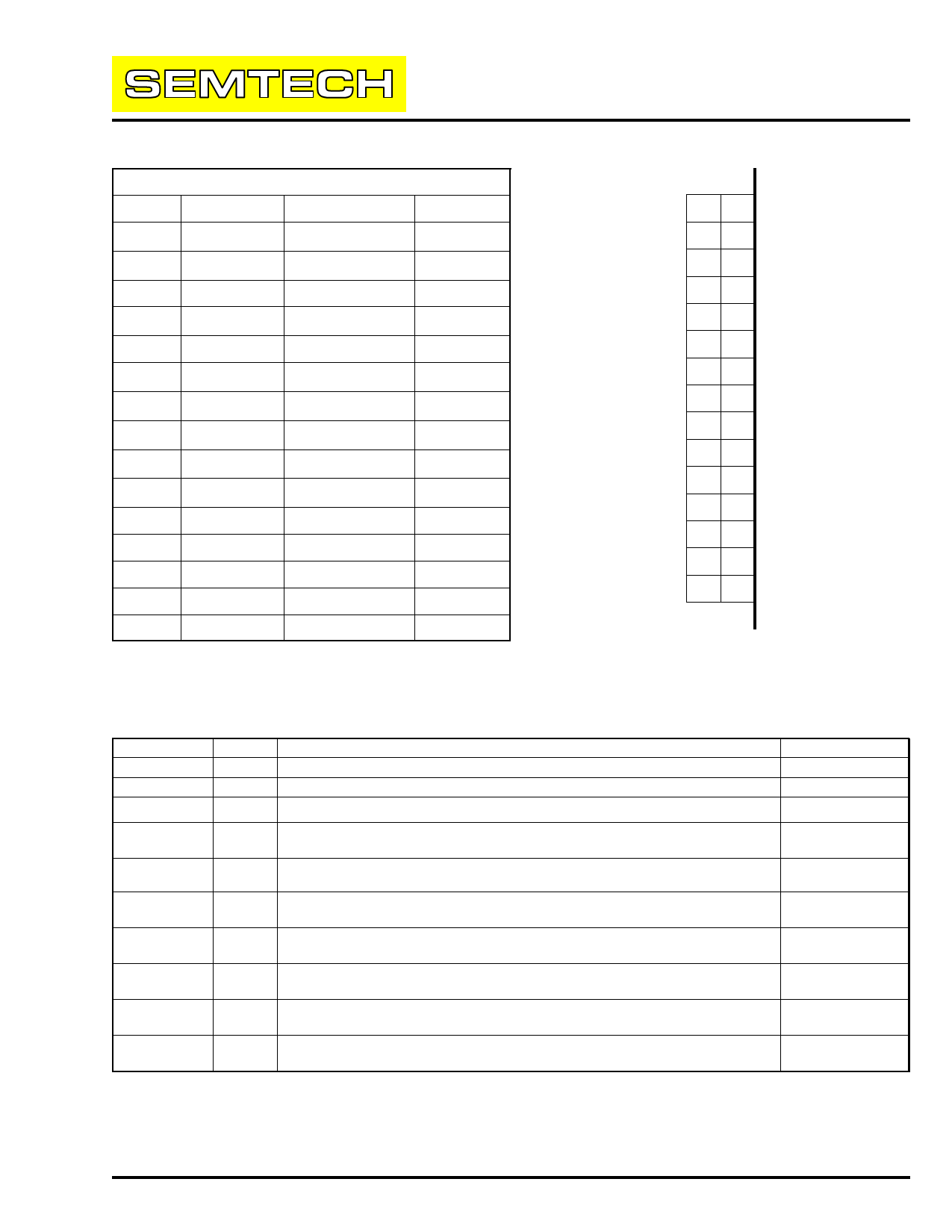
INPUT AND OUTPUT CONNECTIONS
Pin No.
Row A
Row B
1
VSS
2
VSS
3
ND
4
VI/O
5
+3.3V
VSS
VSS
VI/O
VI/O
+3.3V
6
+3.3V
+3.3V
7
VCORE
8
VCORE
9
VSS
10
VCORE
11 PWR GOOD
VCORE
VCORE
VCORE
VCORE
UPVRM#
12
SENSE
DISABLE
13
VSS
14
+5.0V
VSS
+5.0V
15
+5.0V
+5.0V
Pin No.
1
2
3
4
5
6
7
8
9
10
11
12
13
14
15
AB
15
14
13
12
11
10
9
8
7
6
5
4
3
2
1
VRM
PCB
End view of VRM connector
(viewed from motherboard side)
VOLTAGE REGULATOR MODULE CONNECTOR PIN REFERENCE
Pin Name
+3.3V
+5.0V
VCORE
VI/O
VSS
I/O
Input
Input
Output
Output
Input
Function
+3.3V Supply
+5.0V Supply
Voltage Regulator Module Output
CPU I/O power connection. Allows for split voltage plane for I/O
circuitry.
Ground Reference
Notes
Not connected
Input
Output
Tied to output
Ground
DISABLE
PWR
GOOD
SENSE
UPVRM#
ND
Input
Output
Input
Input
When driven high, this input will disable the Voltage Regulator Module
output and the output of the module will float.
Power Good is driven low when the VRM output is not within valid
levels.
Sense is provided for the regulator to correct for voltage drops across
the connector and motherboard powerplane.
This signal indicates to future upgrade processors that the proper
module is installed. This signal must be tied HIGH for this module.
This pin may be used as a +12V supply input, otherwise it should be
left as a no connect (NC)
Not connected
Not connected
Not connected
Tied to output.
Not connected
Note: The functions of DISABLE, SENSE, PWR_GOOD & UPVRM# are optional features specified by Intel. These
are not included in the standard Voltage Regulator Module.
┬® 1997 SEMTECH CORP.
652 MITCHELL ROAD NEWBURY PARK CA 91320
Share Link: 