MC13191 View Datasheet(PDF) - Freescale Semiconductor
Part Name
Description
Manufacturer
MC13191 Datasheet PDF : 24 Pages
| |||
6 Functional Description
6.1 MC13191 Operational Modes
The MC13191 has a number of operational modes that allow for low-current operation. Transition from
the Off Mode to Idle Mode occurs when RST is negated. Once in Idle Mode, the SPI is active and controls
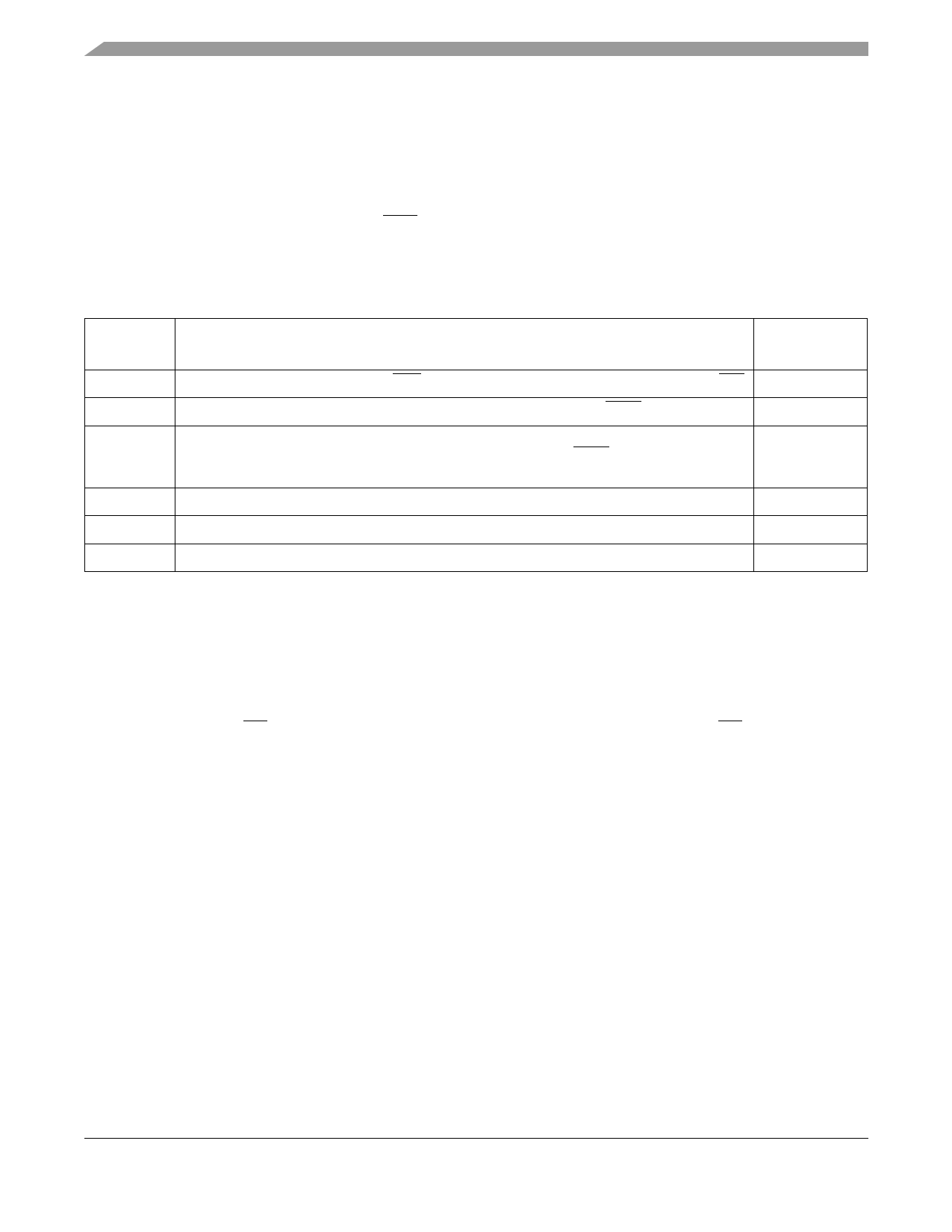
the IC. Transition to Hibernate and Doze modes is enabled via the SPI. Table 7 summarizes these modes,
along with the transition times while Table 3 lists current drain in the various modes.
Table 7. MC13191 Mode Definitions and Transition Times
Mode
Definition
Transition Time
To or From Idle
Off
All IC functions Off, Leakage only. RST asserted. Digital outputs are tri-stated including IRQ 10 - 25 ms to Idle
Hibernate Crystal Reference Oscillator Off. (SPI not functional.) IC Responds to ATTN. Data is retained. 7 - 20 ms to Idle
Doze
Crystal Reference Oscillator On but CLKO output available only if Register 7, Bit 9 = 1 for
frequencies of 1 MHz or less. (SPI not functional.) Responds to ATTN and can be
programmed to enter Idle Mode through an internal timer comparator.
(300 + 1/CLKO)
µs to Idle
Idle
Crystal Reference Oscillator On with CLKO output available. SPI active.
Receive Crystal Reference Oscillator On. Receiver On.
144 µs from Idle
Transmit Crystal Reference Oscillator On. Transmitter On.
144 µs from Idle
6.2 Serial Peripheral Interface (SPI)
The host microcontroller directs the MC13191, checks its status, and reads/writes data to the device
through the 4-wire SPI port. The transceiver operates as an SPI slave device only. A transaction between
the host and the MC13191 occurs as multiple 8-bit bursts on the SPI. The SPI signals are:
1. Chip Enable (CE) - A transaction on the SPI port is framed by the active low CE input signal. A
transaction is a minimum of 3 SPI bursts and can extend to a greater number of bursts.
2. SPI Clock (SPICLK) - The host drives the SPICLK input to the MC13191. Data is clocked into the
master or slave on the leading (rising) edge of the return-to-zero SPICLK and data out changes
state on the trailing (falling) edge of SPICLK.
NOTE
For Freescale microcontrollers, the SPI clock format is the clock phase
control bit CPHA = 0 and the clock polarity control bit CPOL = 0.
3. Master Out/Slave In (MOSI) - Incoming data from the host is presented on the MOSI input.
4. Master In/Slave Out (MISO) - The MC13191 presents data to the master on the MISO output.
A typical interconnection to a microcontroller is shown in Figure 6.
MC13191 Technical Data, Rev. 1.6
10
Freescale Semiconductor
Share Link: 