MC13191 View Datasheet(PDF) - Freescale Semiconductor
Part Name
Description
Manufacturer
MC13191 Datasheet PDF : 24 Pages
| |||
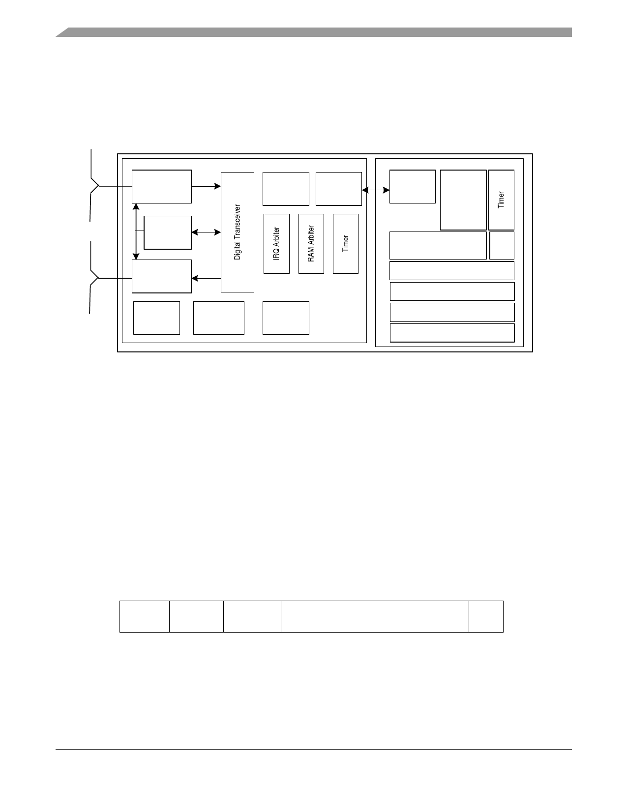
Figure 2 shows the basic system block diagram for the MC13191 in an application. Interface with the
transceiver is accomplished through a 4-wire SPI port and interrupt request line. The media access control
(MAC), drivers, and network and application software (as required) reside on the host processor. The host
can vary from a simple 8-bit device up to a sophisticated 32-bit processor depending on application
requirements.
MC13191
Analog Receiver
Frequency
Generation
Analog
Transmitter
Voltage
Regulators
Power Up
Management
Control
Logic
SPI
and GPIO
Buffer RAM
Microcontroller
SPI
ROM
(Flash)
RAM
CPU
A/D
Application
Network
MAC
PHY Driver
Figure 2. System Level Block Diagram
4 Data Transfer Mode
The MC13191 has a data transfer mode called Packet Mode where data is buffered in on-chip Packet
RAMs. There is a TX Packet RAM and an RX Packet RAM, each of which are 64 locations by 16 bits
wide.
4.1 Packet Structure
Figure 3 shows the packet structure of the MC13191 which is consistent with the 802.15.4 Standard.
Payloads of up to 125 bytes are supported. The MC13191 adds a four-byte preamble, a one-byte Start of
Frame Delimiter (SFD), and a one-byte Frame Length Indicator (FLI) before the data. A two-byte Frame
Check Sequence (FCS) is calculated and appended to the end of the data.
4 bytes
1 byte
Preamble SFD
1 byte
FLI
125 bytes maximum
Payload Data
2 bytes
FCS
Figure 3. MC13191 Packet Structure
MC13191 Technical Data, Rev. 1.6
4
Freescale Semiconductor
Share Link: 