NTE1782 View Datasheet(PDF) - NTE Electronics
Part Name
Description
Manufacturer
NTE1782 Datasheet PDF : 2 Pages
| |||
Electrical Characteristics (Cont’d): (TA = +25°C unless otherwise specified)
Parameter
Symbol
Test Conditions
Min Typ Max Unit
Output Transistor Saturation Voltage V3–2 V3–1 = V7–1 = 24V, Pin2–1 = 33Ω,
–
3.0 4.0
V
V4–1 = 0.3V, V5–1 = 0
V2–1 V3–1 = V7–1 = 24V, Pin2–3 = 33Ω,
–
1.3 2.0
V
V4–1 = 1.3V, V5–1 = 0
Q21 Saturation Voltage
V6–1
V7–1 = 24V, Pin7–6 = 1.2kΩ,
V5–1 = 0
–
– 0.5
V
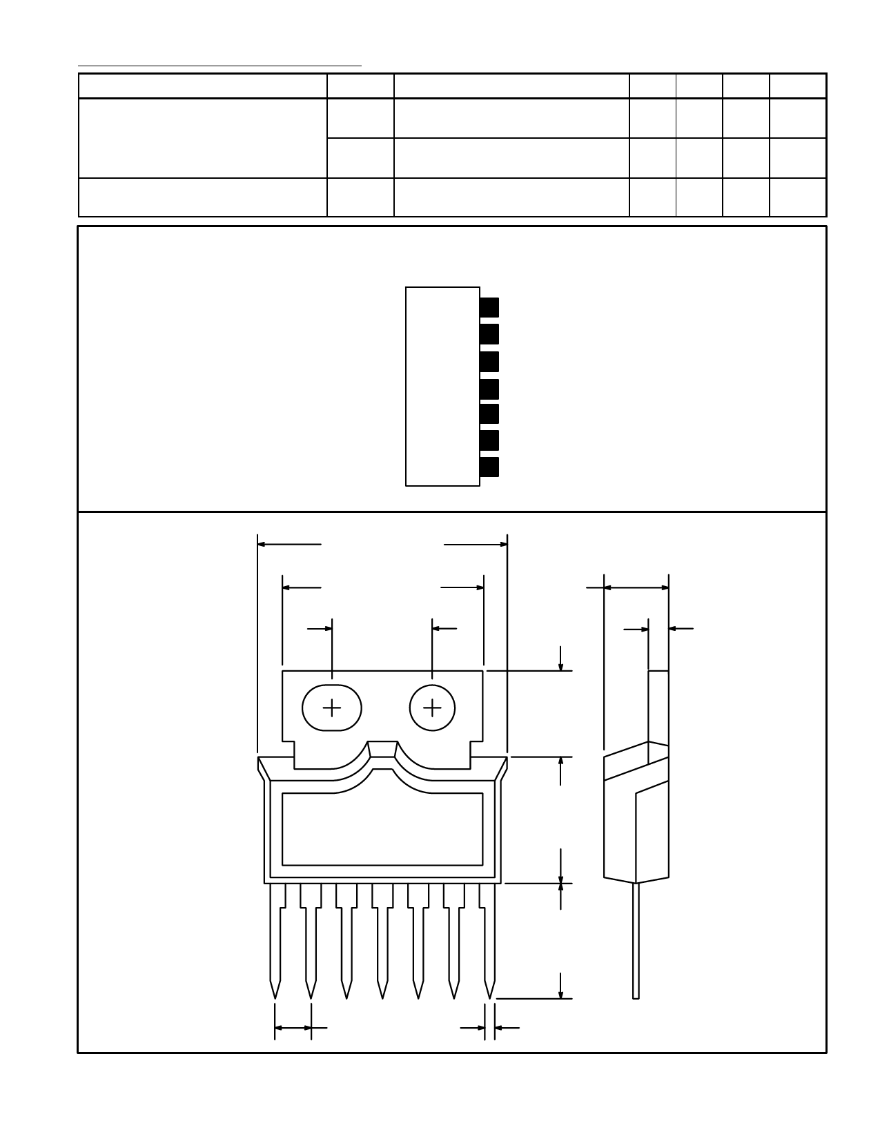
Pin Connection Diagram
(Front View)
7 VCC
6 Pulse Amp Output
5 Trigger Pulse Input
4 Input
3 Supply Voltage for Output
2 Output
1 GND
.697 (17.2)
.602 (15.3)
.300 (7.6)
.138
(3.5)
.233
(5.9)
.047
(1.2)
1
.100 (2.54)
.323
(8.2)
7
.308
(7.8)
.024 (0.6)
Share Link: 