SEL6014_ View Datasheet(PDF) - Sanken Electric co.,ltd.
Part Name
Description
Manufacturer
SEL6014_ Datasheet PDF : 2 Pages
| |||
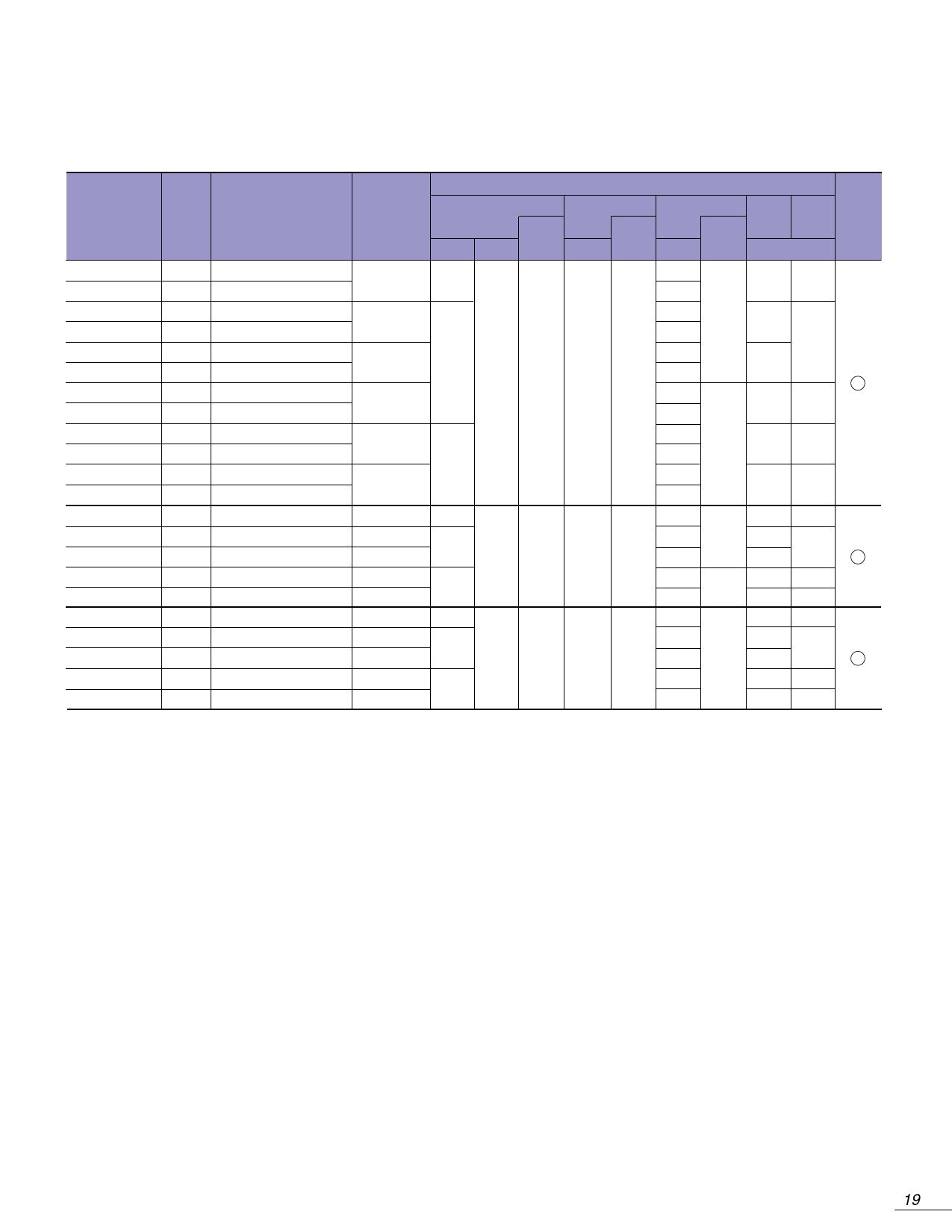
Type No.
SEL6210R
SEL6210S
SEL6410G
SEL6410E
SEL6510G
SEL6510C
SEL6710Y
SEL6710K
SEL6810D
SEL6810A
SEL6910D
SEL6910A
SEL6214S
SEL6414E
SEL6514C
SEL6814A
SEL6914A
SEL6215S
SEL6415E
SEL6515C
SEL6815A
SEL6915A
Display
form
(ø: mm)
q3.1
q3.1
q3.1
q3.1
q3.1
q3.1
q3.1
q3.1
q3.1
q3.1
q3.1
q3.1
q3.5
q3.5
q3.5
q3.5
q3.5
q3.1
q3.1
q3.1
q3.1
q3.1
Type of lens
Red tinted, diffused
Red tinted, non-diffused
Green tinted, diffused
Green tinted, non-diffused
Green tinted, diffused
Un-tinted, non-diffused
Yellow tinted, diffused
Yellow tinted, non-diffused
Orange tinted, diffused
Orange tinted, non-diffused
Orange tinted, diffused
Orange tinted, non-diffused
Red tinted, non-diffused
Green tinted, non-diffused
Un-tinted, non-diffused
Orange tinted, non-diffused
Orange tinted, non-diffused
Red tinted, non-diffused
Green tinted, non-diffused
Un-tinted, non-diffused
Orange tinted, non-diffused
Orange tinted, non-diffused
Emitting
color
High intensity red
Green
Pure green
Yellow
Amber
Orange
High intensity red
Green
Pure green
Amber
Orange
High intensity red
Green
Pure green
Amber
Orange
Electro-optical characteristics (Ta=25°C)
VF
IR
IV
(V)
Condition (µA) Condition (mcd) Condition
IF
VR
IF
typ max (mA) max (V) typ (mA)
λp ∆λ
(nm) typ
12
1.9
630 35
25
2.0
2.5 10 50 3
15
20 560
45
20
5
555
16
5
570 40
15
4
10 610 35
10
1.9
6.5
587 33
14
1.9
10
630 35
2.0
2.5 10 50 3
12 20 560
20
6
555
5
610 35
1.9
10
5
587 33
1.9
30
630 35
2.0
2.5 10 50 3
50
560
20
18 20 555
30
610 35
1.9
40
587 33
Outline
drawing
A
B
C
sUsing contact mount LEDs packaged on tapes
1. Printed circuit board
2. Insertion conditions
3. Soldering conditions
qOne-side printed circuit board is recommended.
qIf there are several SMD parts on the same printed circuit board, insert the LEDs after the adhesive for
other SMD parts hardened.
qUse low insertion pusher pressure, as much as possible.
qCut and clinch: Panasert T pattern is recommended.
For N pattern, make the clinching angle of the LED’s anode as small as possible.
qPreheating must be less than 90°C (temperature on printed circuit board’s bottom surface) for no more
than two minutes
qSolder dipping must be made at a temperature of 250°C for no more than 3 seconds.
19
Share Link: 