MC2833D View Datasheet(PDF) - Motorola => Freescale
Part Name
Description
Manufacturer
MC2833D Datasheet PDF : 8 Pages
| |||
MC2833
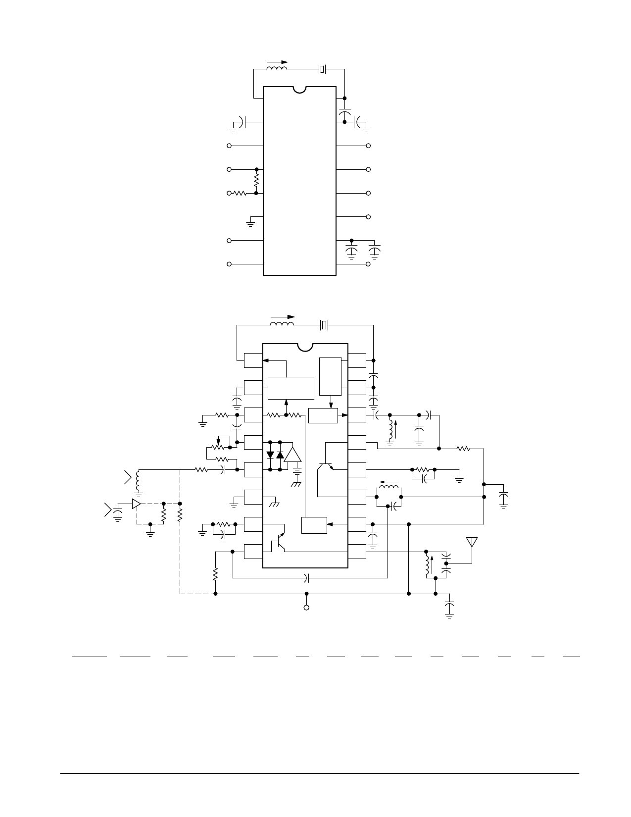
Figure 1. Test Circuit
5.1 µH
Mod Out
1
0.0047 µF
2
Mod In
3
16.605 MHz
16
15
14
39 pF
Crystal: fo = 16.605 MHz
CL = 30 pF
Co = 6.1 pF
RS = 10 Ω Max
68 pF
RF Out
Mic Amp
Out
4
13
220 k
MC2833
Mic Amp
In
5
12
6.3 k
6
11
Base 2
Emitter 2
Collector 2
Emitter 1
7
Base 1
8
10 +
47
µF
9
0.01 µF
Collector 1
Figure 2. Single Chip VHF Narrowband FM Transmitter
Lt
X1
4700 p
100 k
Audio
Input
4700 p
Deviation 100 k
Adjust 120 k
Dynamic
Mike
2.7 k 1.0 µ
1.0 k
Electret
(alternate)
Microphone
and biasing
4.7 k
Re1
470 p
Rb1
1
RF
2
Variable
Osc.
Reactance
3
Mic Amp
4
–+
5
Buffer
Q2
6
7
VREF
Q1
8
Cc2
16
56 p
15
51 p
14
47 p 0.22
µ
13
Cc1
C1
390 k
1.0 k
12
L1
C2
11
1000 p
10
470 p
9
C3
L2
RF Output
C4
5.0 to 10 dBm
(see Note 4)
C5
VCC = 9.0 Vdc
+
1.0 µF
tantalum
NOTES:
1. Components versus output frequency:
Output RF X1 (MHz) Lt (µH)
L1 (µH) L2 (µH)
Re1
Rb1
Cc1
Cc2
C1
C2
C3
C4
C5
49.7 MHz 16.5667
3.3–4.7
0.22
0.22
330 390 k
33 p
33 p
33 p 470 p
33 p
47 p 220 p
76 MHz
12.6000
5.1
0.22
0.22
150 300 k
68 p
10 p
68 p 470 p
12 p
20 p 120 p
144.6 MHz 12.05
5.6
0.15
0.10
150 220 k
47 p
10 p
68 p 1000 p
18 p
12 p
33 p
2. Crystal X1 is fundamental mode, calibrated for parallel resonance with a 32 pF load. The final output frequency is generated by frequency multiplication within
2. the MC2833 IC. The RF output buffer (Pin 14) and Q2 transistor are used as a frequency tripler and doubler, respectively, in the 76 and 144.6 MHz transmitters.
2. The Q1 output transistor is a linear amplifier in the 49.7 MHz and 76 MHz transmitters, and a frequency doubler in the 144.6 MHz transmitter.
3. All coils used are 7 mm shielded inductors, CoilCraft series M1175A, M1282A–M1289A, M1312A or equivalent.
4. Power output is ≈ + 10 dBm for 49.7 MHz and 76 MHz transmitters, and ≈ + 5.0 dBm for the 144.6 MHz transmitter at VCC = 8.0 V. Power output drops with
4. lower VCC.
5. All capacitors in microfarads, inductors in Henries and resistors in Ohms unless otherwise specified.
6. Other frequency combinations may be set–up by simple scaling of the 3 examples shown.
MOTOROLA ANALOG IC DEVICE DATA
3
Share Link: 