LXM1611-01 View Datasheet(PDF) - Microsemi Corporation
Part Name
Description
Manufacturer
LXM1611-01 Datasheet PDF : 5 Pages
| |||
RangeMAXTM
PRODUCT DATABOOK 1996/1997
DIGITAL DIMMING CCFL INVERTER MODULE
Production Data Sheet
LXM1611-01
H O W R A N G E M A X W O R K S (continued)
HIGHLIGHTS
s On-board brightness control circuit includes a DC voltage
to pulse width converter that minimizes system design work
and system noise susceptibility. This provides a familiar
and convenient interface while reducing the potential for
externally induced noise which can cause lamp flicker.
s An on-board oscillator operates the inverter BURST rate
above 95Hz, well beyond standard 50/60Hz video refresh
rates where the eye can perceive pulsing light.
s RangeMAX inverter modules are designed to operate with
the burst frequency synchronized to the video frame rate.
This provides operation with no visible display disturbances
caused by beat frequencies between the lamps and video
frame rates.
s In applications with no access to a vertical sync, the in-
verter burst frequency can be allowed to "free run" at 95Hz.
In this non-synchronous mode, minor display disturbances
can be found under certain video conditions. This perfor-
mance may be acceptable for many applications, but syn-
chronization must be used when no disturbance can be
tolerated.
s Separate inputs are provided for negative and positive ver-
tical sync pulses so external inversion is not needed.
s Separate feedback loops for lamp current and open circuit
voltage regulation insure reliable strike under all operat-
ing conditions, automatic over-voltage prevention with bro-
ken or failed lamps, and accurate lamp current regulation.
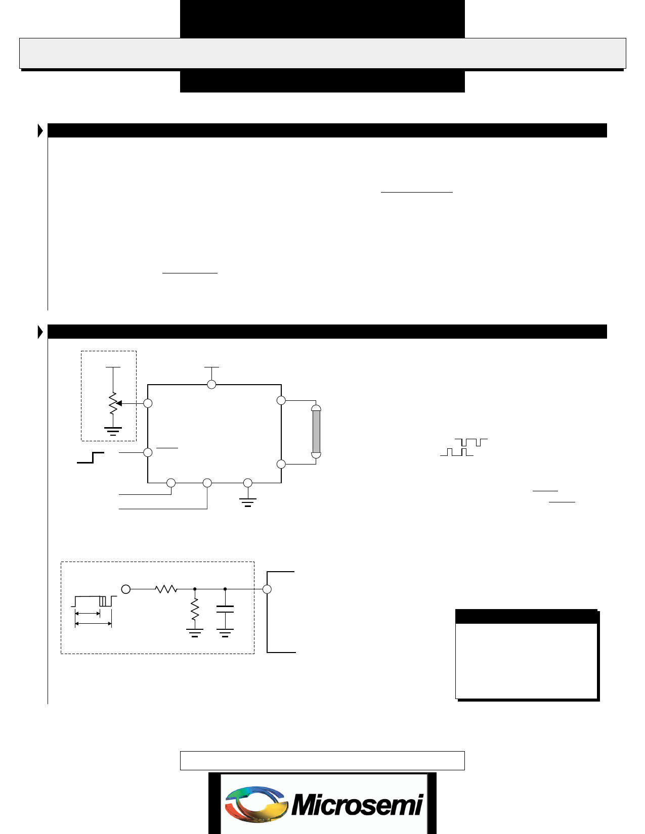
TYPICAL APPLICATION
2.5VDC
9-18VDC
£ 10k
VIN
BRITE
VHI
LXM1611-01
5V
0V
VSYNC(-)
VSYNC(+)
SLEEP
V V SYNC(-)
SYNC(+)
GND VLO
FIGURE 5 — Potentiometer Brightness Control
CCFL
TUBE
PWM Signal
from System
P.W.
4.99k
4.99k*
4.7µF
£ 100µs
0 £ P.W. £ 100% of period
* Use 4.99k for 5V PWM amplitude, 15k for 3.3V PWM
amplitude, and omit for 2.5V PWM amplitude.
BRITE
LXM1611-01
FIGURE 5A — PWM Brightness Control
s The brightness control may be a simple 10k
potentiometer or a voltage output DAC. A PWM signal
from a micro-controller may also be used with a suitable
filter such as shown in Figure 5A.
s If synchronization to the video framerate is desired,
connect the vertical sync pulse from the system video
controller to the appropriate VSYNC input. If the pulse
is negative going (
), connect it to V . If
SYNC(-)
positive going (
), connect it to VSYNC(+).
If no video synchronization is desired, leave both VSYNC(-)
and V floating.
SYNC(+)
s If you need to turn the inverter ON/OFF remotely,
connect a 3V or 5V logic signal to the SLEEP input. If
remote ON/OFF is not needed, connect the SLEEP input
to V or any other voltage greater than 2.2V .
IN
DC
s Connect V to high voltage wire from the lamp.
HI
Connect V to the low voltage wire (wire with thinner
LO
insulation). Never connect V to circuit ground as
LO
this will defeat lamp current regulation. If both lamp
wires have heavy high voltage insulation, connect the
longest wire to V .
LO
RangeMAX INVERTERS
Also available in Dual
Output LXM1621-01 and
Quad Output LXM1641-01
versions for multiple lamp
applications.
RangeMAX and Direct Drive are trademarks of Linfinity Microelectronics Inc.
PRELIMINARY DATA - Information contained in this document is pre-production data, and is proprietary to LinFinity. It may
not modified in any way without the express written consent of LinFinity. Product referred to herein is offered in sample form
only, and Linfinity reserves the right to change or discontinue this proposed product at any time.
Copyright © 1999
Rev. 1.0 1/05
5
Share Link: 