IS43TR16640A(2016) View Datasheet(PDF) - Integrated Silicon Solution
Part Name
Description
Manufacturer
IS43TR16640A Datasheet PDF : 87 Pages
| |||
IS43/46TR16640A, IS43/46TR16640AL
IS43/46TR81280A, IS43/46TR81280AL
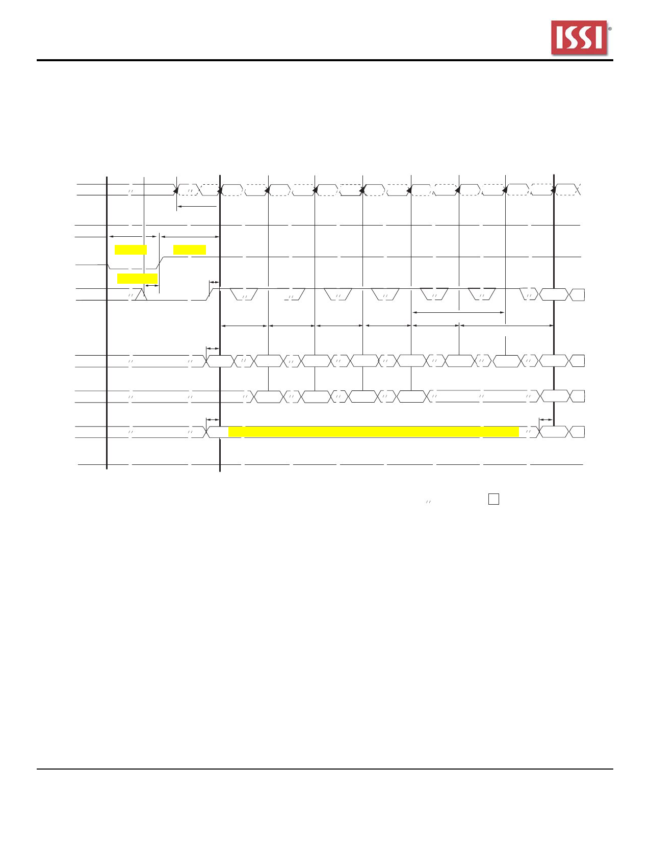
9. Issue MRS Command to load MR0 with all application settings and “DLL reset”. (To issue DLL reset command,
provide "High" to A8 and "Low" to BA0-2).
10. Issue ZQCL command to starting ZQ calibration.
11. Wait for both tDLLK and tZQinit completed.
12. The DDR3 SDRAM is now ready for normal operation.
CK,CK#
VDD,VDDQ
Ta
Tb
((
)( ()
))
((
))
Tc
Td
Te
Tf
Tg
Th
Ti
Tj
Tk
((
((
((
((
((
((
((
((
)( ()
)( ()
)( ()
)( ()
)( ()
)( ()
)( ()
)( ()
))
))
))
))
))
))
))
))
tCKSRX
((
((
))
))
((
((
((
))
))
))
((
((
((
))
))
))
RESET#
CKE
T=200µS
T=5(0(0µS
((
((
))
))
))
Tmin=10nS
((
tIS
((
)( ()
)( ()
))
))
((
((
((
))
))
))
((
((
((
)( ()
)( ()
)( ()
))
))
))
((
((
))
))
((
((
)( ()
)( ()
))
))
tDLLK
((
))
((
)( () Valid
))
((
CMMAND
)( ()
))
((
BA
)( ()
))
((
ODT
)( ()
))
tXPR
tIS
tMRD
tMRD
tMRD
tMOD
tZQinit
((
((
((
((
((
((
((
((
)( ()
1) )( () MRD )( () MRD )( () MRD )( () MRD )( () ZQCL )( () 1) )( () Valid
))
))
))
))
))
))
))
))
((
((
((
((
((
((
((
((
)( ()
)( () MR2 )( () MR3 )( () MR1 )( () MR0 )( ()
)( ()
)( () Valid
))
))
))
))
))
))
))
))
tIS
tIS
((
((
((
((
)( ()
Stat)(i()c LOW in case RTT_Nom is enabled at time Tg, otherwise static HIG)( H() or LOW )( () Valid
))
))
))
))
RTT
((
((
((
((
((
((
((
((
))
))
))
))
))
))
))
))
Note1. From time point “Td” until “Tk” NOP or DES commands must be
applied between MRS and ZQCL commands.
( ( Time
) ) Break
Figure2.1.1 Reset and Initialization Sequence at Power-on Ramping
((
))
DON’T
CARE
2.2.2 Reset Initialization with Stable Power
The following sequence is required for RESET at no power interruption initialization.
1. Asserted RESET below 0.2 * VDD anytime when reset is needed (all other inputs may be undefined). RESET needs
to be maintained for minimum 100 ns. CKE is pulled “LOW” before RESET being de-asserted (min. time 10 ns).
2. Follow Power-up Initialization Sequence steps 2 to 11.
3. The Reset sequence is now completed; DDR3 SDRAM is ready for normal operation.
Integrated Silicon Solution, Inc. – www.issi.com –
7
Rev. J
03/14/2016
Share Link: 