TC654 View Datasheet(PDF) - Microchip Technology
Part Name
Description
Manufacturer
TC654 Datasheet PDF : 38 Pages
| |||
TC654/TC655
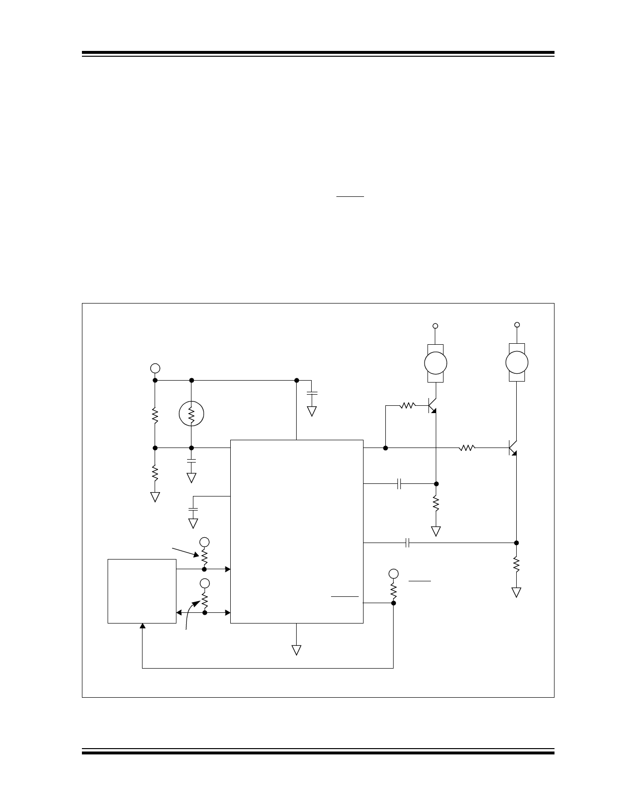
4.0 DEVICE OPERATION
The TC654 and TC655 devices allow you to control,
monitor and communicate (via SMBus) fan speed for 2-
wire and 3-wire DC brushless fans. By pulse-width
modulating (PWM) the voltage across the fan, the
TC654/TC655 controls fan speed according to the sys-
tem temperature.The goal of temperature proportional
fan speed control is to reduce fan power consumption,
increase fan life and reduce system acoustic noise.
With the TC654 and TC655 devices, fan speed can be
controlled by the analog input VIN or the SMBus inter-
face, allowing for high system flexibility.
The TC654 and TC655 also measure and monitor fan
revolutions per minute (RPM). A fan’s speed (RPM) is
a measure of its health. As a fan’s bearings wear out,
the fan slows down and eventually stops (locked rotor).
By monitoring the fan’s RPM level, the TC654/TC655
devices can detect open, shorted, unconnected and
locked rotor fan conditions. The fan speed threshold
can be set to provide a predictive fan failure feature.
This feature can be used to give a system warning and,
in many cases, help to avoid a system thermal shut-
down condition. The fan RPM data and threshold reg-
isters are available over the SMBus interface which
allows for complete system control.
The TC654/TC655 devices are identical in every
aspect except for how they indicate an over-tempera-
ture condition. When VIN voltage exceeds 2.6V (typi-
cal), both devices will set OTF (bit 5<X>) in the Status
Register to a '1'. The TC655 will additionally pull the
FAULT output low during an over-temperature condi-
tion.
+12V
+5V
+5V
FAN
FAN
1
2
R1
34.8 k
R2
14.7 k
NTC Thermistor
100 k @ 25°C
1 VIN
C1
0.01 µF
2
CF
CF 1.0 µF
C2
1 µF
RISO1
10
VDD
9
VOUT
715
8 CSENSE1
SENSE1
0.1 µF
RSCLK +5V
20 k
PIC®
+5V
Microcontroller
RSDA
20 k
TC654/TC655
SENSE2 7
CSENSE2
3
SCLK
4 SDA
GND
5
0.1 µF
+5V
6
FAULT
RFAULT
20 k
RISO2
715
RSENSE1
RSENSE2
Note: Refer to Table 7-1 for RSENSE1 and RSENSE2 values.
FIGURE 4-1:
Typical Application Circuit.
2002-2014 Microchip Technology Inc.
DS20001734C-page 9
Share Link: 