MB91107 View Datasheet(PDF) - Fujitsu
Part Name
Description
Manufacturer
MB91107 Datasheet PDF : 96 Pages
| |||
MB91107/108
• Notes on using the STOP mode
The regulator built in this product stops in the STOP mode. If the regulator stops due to a malfunction caused
by noise or a fault in the power supply during normal operation, the internal 2.5-V power supply may go below
the lower limit of the guaranteed operating voltage range. When using the STOP mode with the internal regulator,
therefore, be sure to supply an auxiliary external power to prevent the 3.3-V power supply from coming down.
Even in that case, the internal regulator can be restarted by input of a reset signal (To restart the regulator, keep
the reset pin at the L level for at least the oscillation settling time).
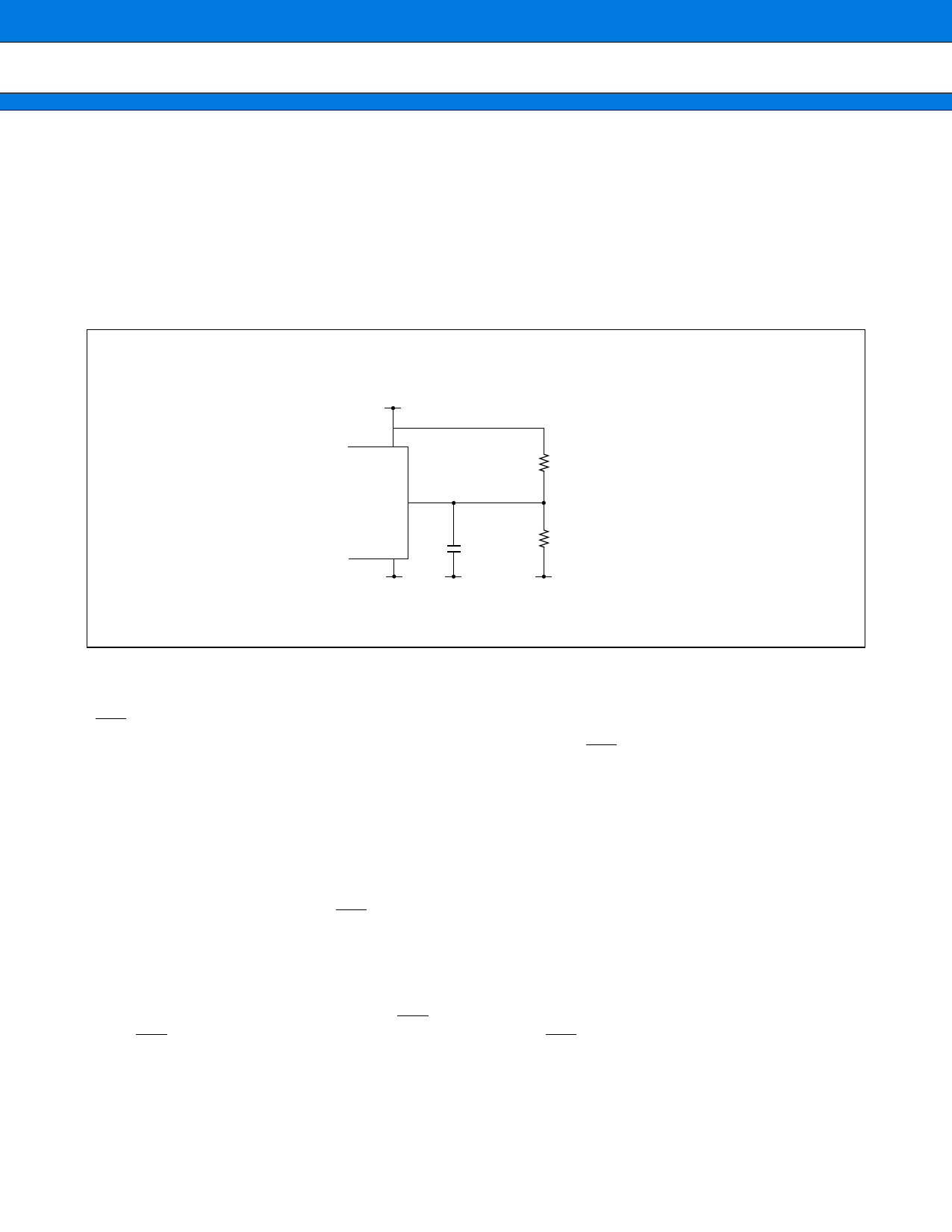
•Using STOP mode with 3.3 V power supply
3.3 V
VCC
C
VSS
0.1 µF
2.4 kΩ
7.6 kΩ
5. Turning on the Power Supply
•RST pin
When turning on the power supply, never fail to start from setting the RST pin to “L” level. And after the power
supply voltage goes to VCC level, at least after ensuring the time for 5 machine cycles, then set to “H” level.
•Pin Condition at Turning on the Power Supply
The pin condition at turning on the power supply is unstable. The circuit starts being initialized after turning on
the power supply and then starting oscillation and then the operation of the internal regulator becomes stable.
So it takes about 42 ms for the pin to be initialized from the oscillation starting at the source oscillation 12.5 MHz.
Take care that the pin condition may be output condition at initial unstable condition.
(With the MB91107, however, initalization can be achieved in less than about 42 ms after turning on the internal
power supply by maintaining the RST pin at "L" level.)
•Source Oscillation Input at Turning on the Power Supply
At turning on the power supply, never fail to input the clock before cancellation of the oscillation stabilizing waiting.
•Hardware Stand-by at Turning on the Power Supply
When turning on the power supply with the HST pin being set to “L” level, the hardware doesn’t stand by. However
the HST pin becomes available after the reset cancellation, the HST pin must once be back to “H” level.
•Power on Reset
Make sure to make power on reset at turning on the power supply or returning on the power supply when the
power supply voltage is below the warranty range for normal operation.
16
Share Link: 