TEMT1000 View Datasheet(PDF) - Vishay Semiconductors
Part Name
Description
Manufacturer
TEMT1000 Datasheet PDF : 9 Pages
| |||
TEMT1000, TEMT1020, TEMT1030, TEMT1040
www.vishay.com
Vishay Semiconductors
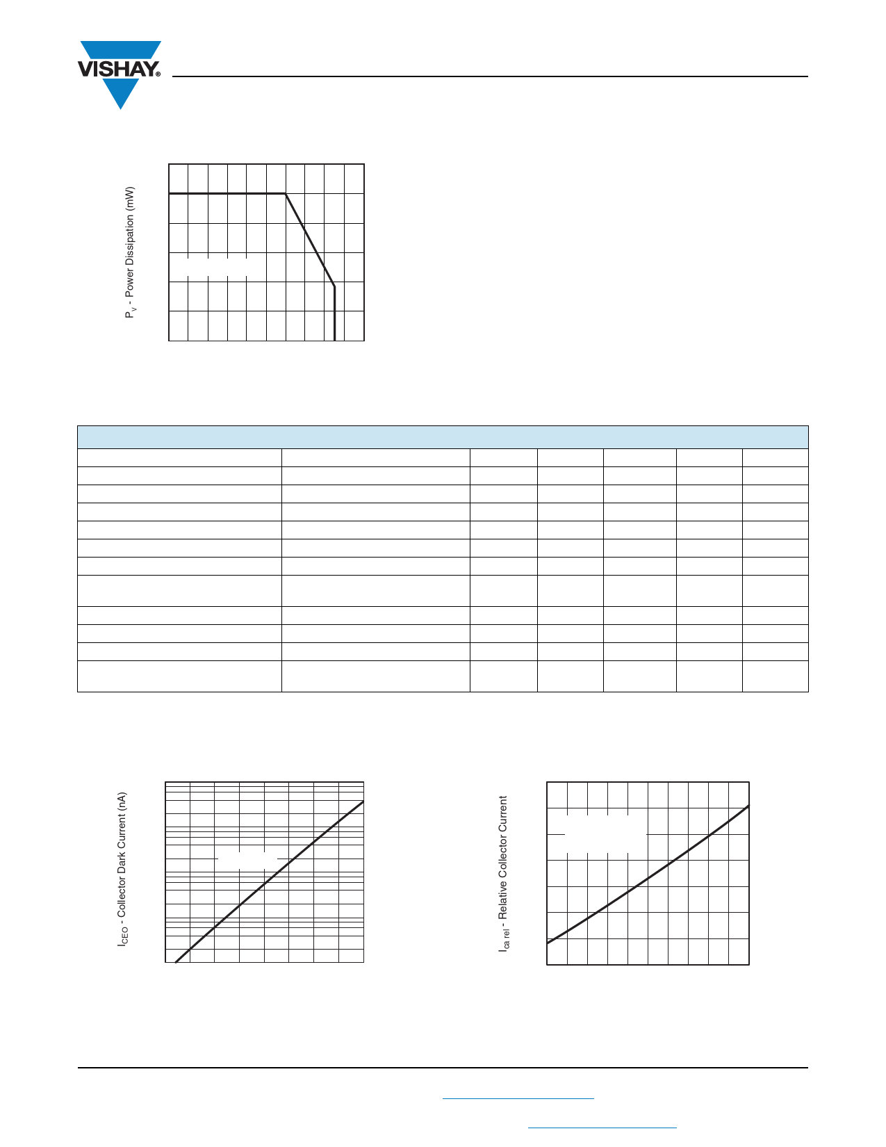
120
100
80
60
RthJA = 400 K/W
40
20
0
0
21167
10 20 30 40 50 60 70 80 90 100
Tamb - Ambient Temperature (°C)
Fig. 1 - Power Dissipation Limit vs. Ambient Temperature
BASIC CHARACTERISTICS (Tamb = 25 °C, unless otherwise specified)
PARAMETER
TEST CONDITION
SYMBOL MIN.
Collector emitter voltage
IC = 1 mA
VCEO
70
Collector emitter dark current
Collector emitter capacitance
Angle of half sensitivity
VCE = 20 V, E = 0
VCE = 5 V, f = 1 MHz, E = 0
ICEO
CCEO
Wavelength of peak sensitivity
p
Range of spectral bandwidth
0.5
Collector emitter saturation voltage
Ee = 1 mW/cm2, = 950 nm,
IC = 0.1 mA
VCEsat
Turn-on time
VS = 5 V, IC = 5 mA, RL = 100
ton
Turn-off time
VS = 5 V, IC = 5 mA, RL = 100
toff
Cut-off frequency
VS = 5 V, IC = 5 mA, RL = 100
fc
Collector light current
Ee = 1 mW/cm2, = 950 nm,
VCE = 5 V
Ica
2
TYP.
1
3
± 15
880
730 to 1000
2.0
2.3
180
7.0
MAX.
200
0.3
BASIC CHARACTERISTICS (Tamb = 25 °C, unless otherwise specified)
UNIT
V
nA
pF
deg
nm
nm
V
μs
μs
kHz
mA
104
103
VCE = 20 V
102
101
10
20
40
60
80
100
94 8304
Tamb - Ambient Temperature (°C)
Fig. 2 - Collector Dark Current vs. Ambient Temperature
2.0
1.8
VCE = 5 V
1.6
Ee = 1 mW/cm2
λ = 950 nm
1.4
1.2
1.0
0.8
0.6
0
20
40
60
80
100
94 8239
Tamb - Ambient Temperature (°C)
Fig. 3 - Relative Collector Current vs. Ambient Temperature
Rev. 1.6, 29-Jun-11
2
Document Number: 81554
For technical questions, contact: detectortechsupport@vishay.com
THIS DOCUMENT IS SUBJECT TO CHANGE WITHOUT NOTICE. THE PRODUCTS DESCRIBED HEREIN AND THIS DOCUMENT
ARE SUBJECT TO SPECIFIC DISCLAIMERS, SET FORTH AT www.vishay.com/doc?91000
Share Link: 