MC7410VU400LE View Datasheet(PDF) - Unspecified
Part Name
Description
Manufacturer
MC7410VU400LE Datasheet PDF : 56 Pages
| |||
Electrical and Thermal Characteristics
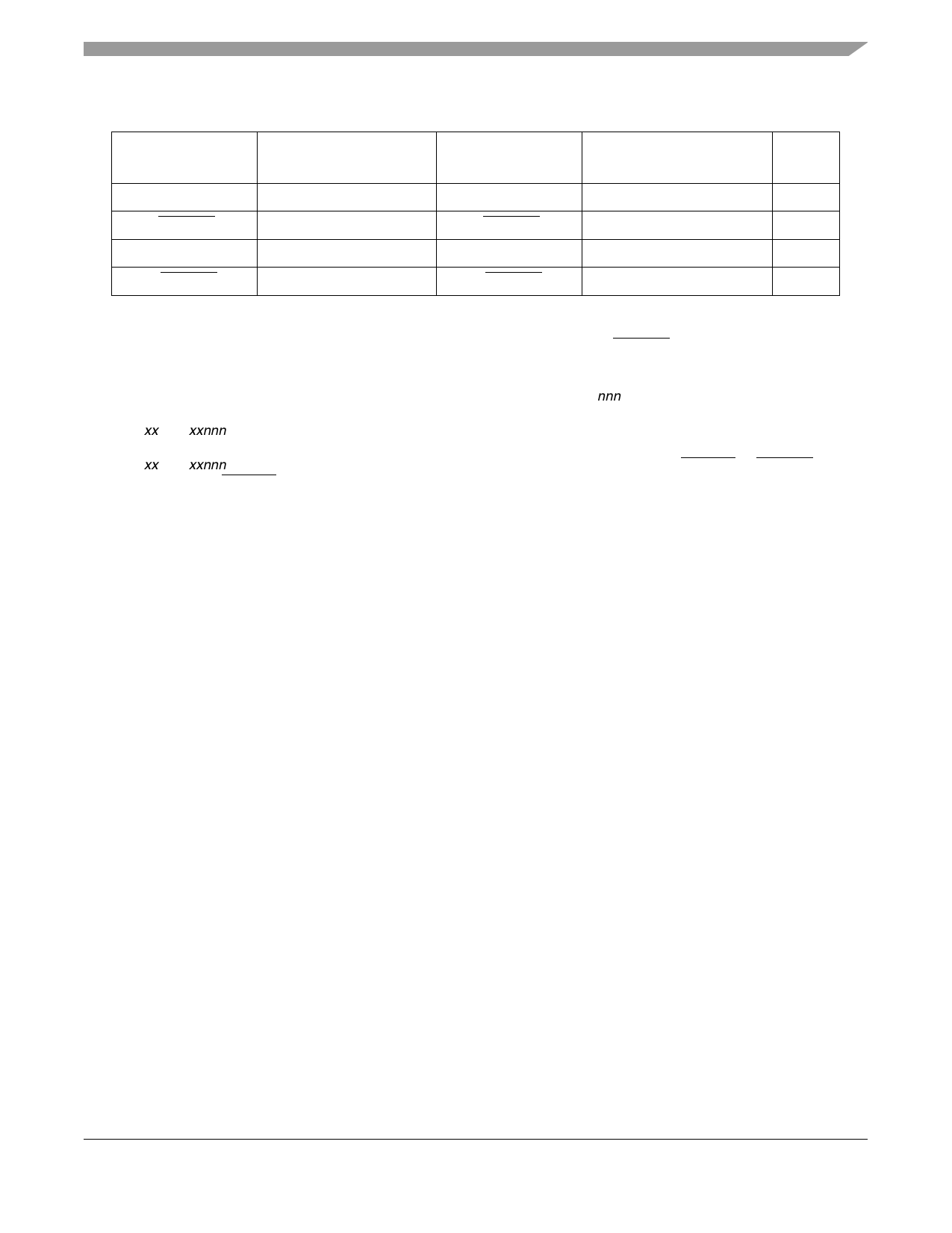
Table 2. Input Threshold Voltage Setting
BVSEL Signal 3
Processor Bus Input
Threshold is Relative to:
L2VSEL Signal 3
L2 Bus Input Threshold is
Relative to:
Notes
0
1.8 V
0
1.8 V
1
HRESET
2.5 V
HRESET
2.5 V
1, 2
1
3.3 V
1
2.5 V
1, 4, 5
¬HRESET
3.3 V
¬HRESET
Not Supported
6
Notes:
1. Caution: The input threshold selection must agree with the OVDD/L2OVDD voltages supplied.
2. To select the 2.5-V threshold option, BVSEL and/or L2VSEL should be tied to HRESET so that the two signals
change state together. This is the preferred method for selecting this mode of operation.
3. To overcome the internal pull-up resistance, a pull-down resistance less than 250 Ω should be used.
4. Default voltage setting if left unconnected (internal pulled-up). MPC7410RXnnnLE (Rev 1.4) and later only.
Previous revisions do not support 3.3 V OVDD; the default voltage setting if left unconnected is 2.5 V.
5. Mxx7410xxnnnLE (Rev. 1.4) and later only. Previous revisions do not support 3.3 V OVDD; having BVSEL = 1 selects
the 2.5-V threshold.
6. Mxx7410xxnnnLE (Rev. 1.4) and later only. Previous revisions do not support BVSEL = ¬HRESET. (¬HRESET is
the inverse of HRESET.)
Table 3 provides the recommended operating conditions for the MPC7410.
MPC7410 RISC Microprocessor Hardware Specifications, Rev. 6.1
Freescale Semiconductor
9
Share Link: 