DCR1277SD View Datasheet(PDF) - Dynex Semiconductor
Part Name
Description
Manufacturer
DCR1277SD Datasheet PDF : 9 Pages
| |||
DCR1277SD
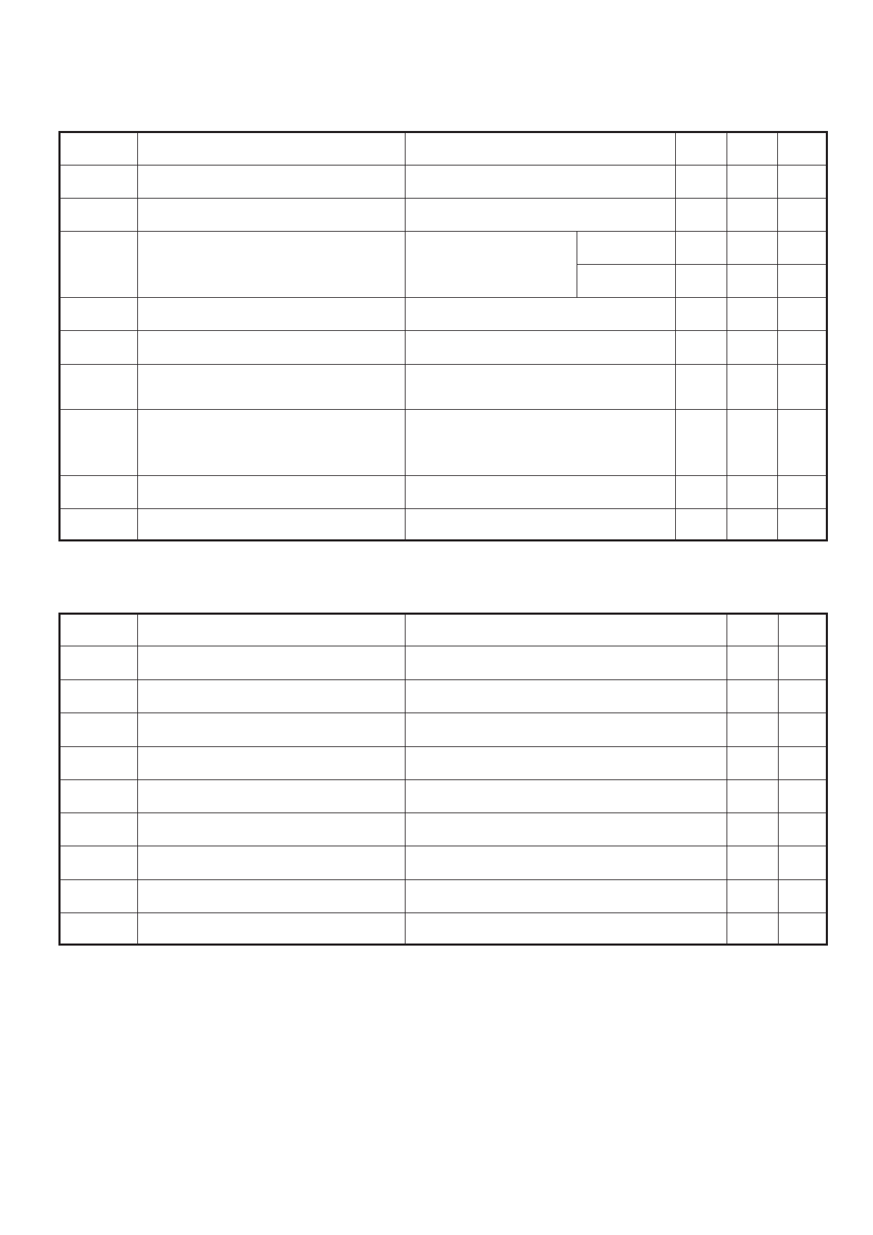
DYNAMIC CHARACTERISTICS
Symbol
Parameter
Conditions
Typ. Max. Units
IRRM/IDRM
dV/dt
Peak reverse and off-state current
At VRRM/VDRM, Tcase = 125oC
Maximum linear rate of rise of off-state voltage To 67% VDRM Tj = 125oC.
-
150 mA
-
300 V/µs
dI/dt Rate of rise of on-state current
V
T(TO)
rT
t
gd
Threshold voltage
On-state slope resistance
Delay time
tq
Turn-off time
From 67% V to 1000A Repetitive 50Hz -
DRM
Gate source 10V, 5Ω
t
r
≤
0.5µs,
T
j
=
125oC
Non-repetitive -
At T = 125oC
-
vj
At Tvj = 125oC
-
V
D
=
67%
V,
DRM
Gate
source
30V,
15Ω
t
r
=
0.5µs,
T
j
=
25oC
-
I
T
=
2000A,
tp
=
1ms,
Tj
=
125˚C,
VR = 50V, dIRR/dt = 5A/µs,
500
VDR = 67% VDRM, dVDR/dt = 20V/µs linear
100 A/µs
150 A/µs
0.95 V
0.45 mΩ
2.5
µs
650 µs
IL
Latching current
IH
Holding current
Tj = 25oC, VD = 5V
Tj = 25oC, Rg-k = ∞
700 1000 mA
200 500 mA
GATE TRIGGER CHARACTERISTICS AND RATINGS
Symbol
Parameter
VGT
IGT
V
GD
VFGM
VFGN
V
RGM
IFGM
PGM
PG(AV)
Gate trigger voltage
Gate trigger current
Gate non-trigger voltage
Peak forward gate voltage
Peak forward gate voltage
Peak reverse gate voltage
Peak forward gate current
Peak gate power
Mean gate power
Conditions
VDRM = 5V, Tcase = 25oC
VDRM = 5V, Tcase = 25oC
At V T = 125oC
DRM case
Anode positive with respect to cathode
Anode negative with respect to cathode
Anode positive with respect to cathode
See table, fig.4
Max. Units
4.0
V
400 mA
0.25 V
30
V
0.25 V
5
V
10
A
150 W
5
W
3/9
Share Link: 