7C1325-100 View Datasheet(PDF) - Cypress Semiconductor
Part Name
Description
Manufacturer
7C1325-100 Datasheet PDF : 13 Pages
| |||
ADVANCED INFORMATION
CY7C1325
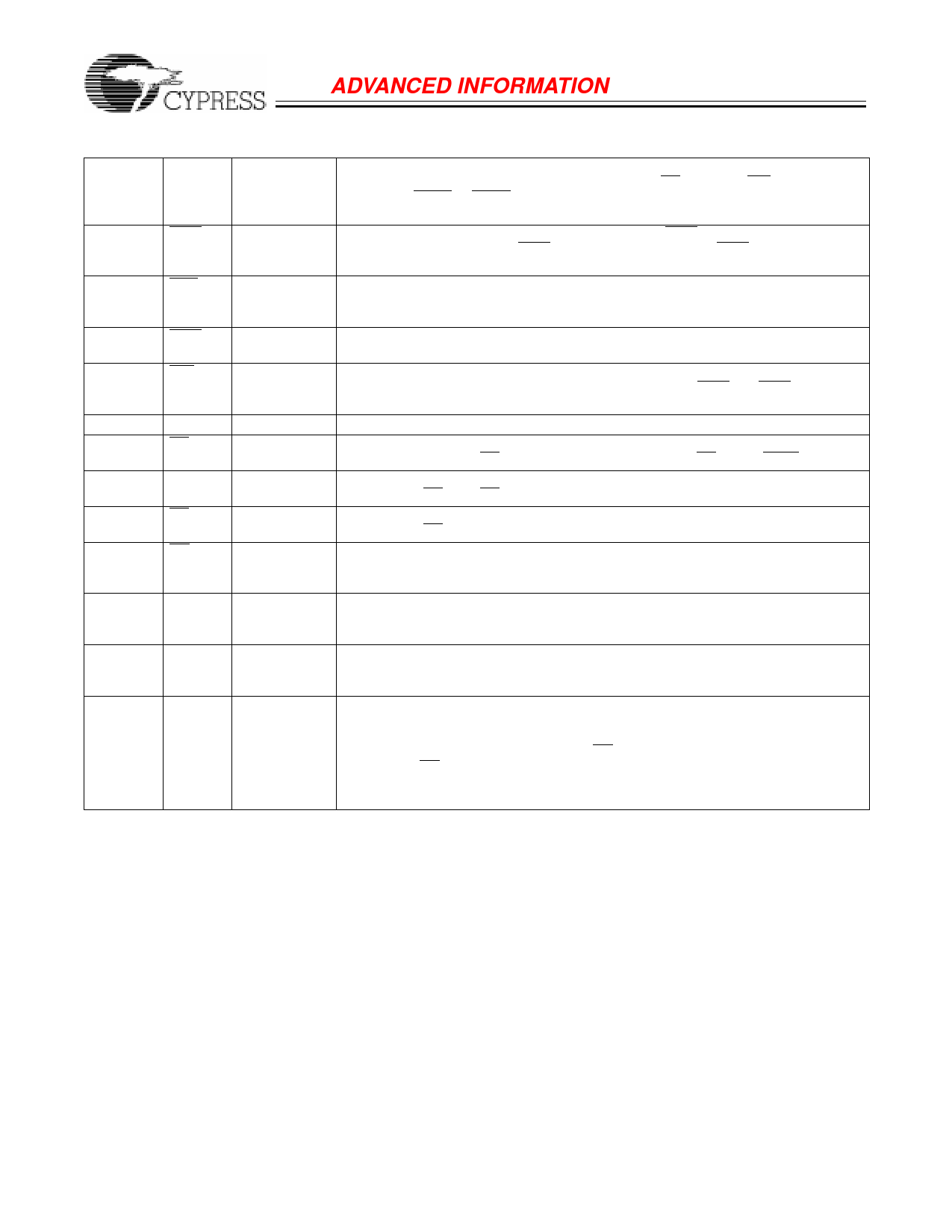
Pin Descriptions (continued)
50–44,
80–82, 99,
100,
32–35
94, 93
A[17:2]
BWS[1:0]
83
ADV
87
BWE
88
GW
89
CLK
98
CE1
97
CE2
92
CE3
86
OE
64
ZZ
31
MODE
23, 22, 19,
18, 13, 12,
9, 8, 73,
72, 69, 68,
63, 62, 59,
58
DQ[15:0]
Input-
Address Inputs used in conjunction with A[1:0] to select one of the 256K address
Synchronous locations. Sampled at the rising edge of the CLK, if CE1, CE2, and CE3 are sampled
active, and ADSP or ADSC is active LOW.
Input-
Synchronous
Input-
Synchronous
Input-
Synchronous
Input-
Synchronous
Input-Clock
Input-
Synchronous
Input-
Synchronous
Input-
Synchronous
Input-
Asynchronous
Input-
Asynchronous
-
I/O-
Synchronous
Byte Write Select Inputs, active LOW. Qualified with BWE to conduct byte writes.
Sampled on the rising edge. BWS0 controls DQ[7:0] and DP0, BWS1 controls DQ[15:8]
and DP1. See write table for further details.
Advance input used to advance the on-chip address counter. When LOW the internal
burst counter is advanced in a burst sequence. The burst sequence is selected using
the MODE input.
Byte Write Enable Input, active LOW. Sampled on the rising edge of CLK. This signal
must be asserted LOW to conduct a byte write.
Global Write Input, active LOW. Sampled on the rising edge of CLK. This signal is
used to conduct a global write, independent of the state of BWE and BWS[1:0]. Global
writes override byte writes.
Clock input. Used to capture all synchronous inputs to the device.
Chip Enable 1 Input, active LOW. Sampled on the rising edge of CLK. Used in con-
junction with CE2 and CE3, to select/deselect the device. CE1 gates ADSP.
Chip Enable 2 Input, active HIGH. Sampled on the rising edge of CLK. Used in con-
junction with CE1 and CE3 to select/deselect the device.
Chip Enable 3 Input, active LOW. Sampled on the rising edge of CLK. Used in con-
junction with CE1 and CE2 to select/deselect the device.
Output Enable, asynchronous input, active LOW. Controls the direction of the I/O pins.
When LOW, the I/O pins behave as outputs. When deasserted HIGH, I/O pins are
three-stated, and act as input data pins.
Snooze input. Active HIGH asynchronous. When HIGH, the device enters a low power
standby mode in which all other inputs are ignored, but the data in the memory array
is maintained.Leaving ZZ floating or NC will default the device into an active state.
Mode input. Selects the burst order of the device. Tied HIGH selects the interleaved
burst order. Pulled LOW selects the linear burst order. When left floating or NC, defaults
to interleaved burst order.
Bidirectional Data I/O lines. As inputs, they feed into an on-chip data register that is
triggered by the rising edge of CLK. As outputs, they deliver the data contained in the
memory location specified by A[17:0] during the previous clock rise of the read cycle.
The direction of the pins is controlled by OE in conjunction with the internal control
logic. When OE is asserted LOW, the pins behave as outputs. When HIGH, DQ[15:0]
and DP[1:0] are placed in a three-state condition. The outputs are automatically
three-stated when a WRITE cycle is detected.
5
Share Link: 