ILX511 View Datasheet(PDF) - Sony Semiconductor
Part Name
Description
Manufacturer
ILX511 Datasheet PDF : 13 Pages
| |||
ILX511
Notes on Handling
1) Static charge prevention
CCD image sensors are easily damaged by static discharge. Before handling, be sure to take the following
protective measures.
a) Either handle bare handed or use non-chargeable gloves, clothes or material. Also use conductive
shoes.
b) When handling directly use an earth band.
c) Install a conductive mat on the floor or working table to prevent the generation of static electricity.
d) Ionized air is recommended for discharge when handling CCD image sensors.
e) For the shipment of mounted substrates use cartons treated for the prevention of static charges.
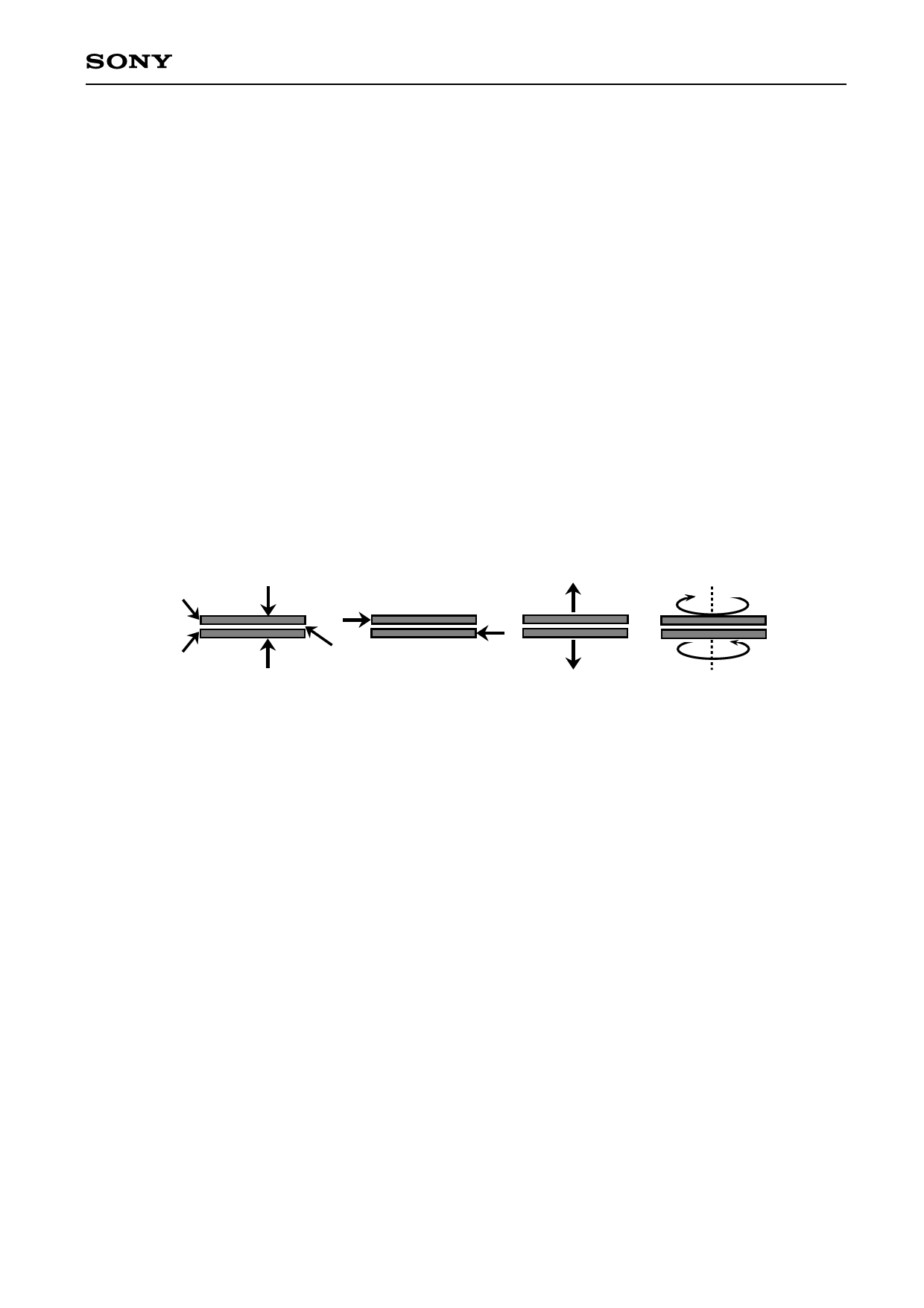
2) Notes on handling CCD Cer-DIP package
The following points should be observed when handling and installing this package.
a) (1) Compressive strength: 39N/surface
(Do not apply any load more than 0.7 mm inside the outer perimeter of the glass
portion.)
(2) Shearing strength:
29N/surface
(3) Tensile strength:
29N/surface
(4) Torsional strength:
0.9Nm
Upper ceramic layer
39N
29N
0.9Nm
29N
Lower ceramic layer
Low-melting glass
(1)
(2)
(3)
(4)
b) In addition, if a load is applied to the entire surface by a hard component, bending stress may be
generated and the package may fracture, etc., depending on the flatness of the ceramic portion.
Therefore, for installation, either use an elastic load, such as a spring plate, or an adhesive.
c) Be aware that any of the following can cause the glass to crack because the upper and lower ceramic
layers are shielded by low-melting glass.
(1) Applying repetitive bending stress to the external leads.
(2) Applying heat to the external leads for an extended period of time with a soldering iron.
(3) Rapid cooling or heating.
(4) Applying a load or impact to a limited portion of the low-melting glass with a small-tipped tool such
as tweezers.
(5) Prying the upper or lower ceramic layers away at a support point of the low-melting glass.
Note that the preceding notes should also be observed when removing a component from a board
after it has already been soldered.
3) Soldering
a) Make sure the package temperature does not exceed 80 °C.
b) Solder dipping in a mounting furnace causes damage to the glass and other defects. Use a grounded
30W soldering iron and solder each pin in less than 2 seconds. For repairs and remount, cool
sufficiently.
c) To dismount image sensors, do not use a solder suction equipment. When using an electric
desoldering tool, ground the controller. For the control system, use a zero cross type.
—11—
Share Link: 