HER1601CTD View Datasheet(PDF) - Unspecified
Part Name
Description
Manufacturer
HER1601CTD Datasheet PDF : 3 Pages
| |||
HER1601CT THRU HER1608CT
GLASS PASSIVATED HIGH EFFICIENCY RECTIFIER
REVERSE VOLTAGE:
50 to 1000 VOLTS
FORWARD CURRENT:
16.0 AMPERE
FEATURES
· Plastic package has Underwriters Laboratory
Flammability Classification 94V-O ctilizing
Flame Retardant Epoxy Molding Compound.
· Low power loss, high efficiency.
· Low forward voltage, high current capability
· High surge capacity.
· Ultra fast recovery times, high voltage.
· Exceeds environmental standards of MIL-S-19500/228
MECHANICAL DATA
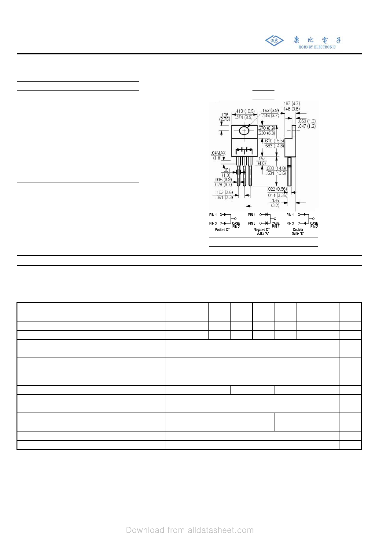
Case: Molded plastic, TO-220
Epoxy: UL 94V-O rate flame retardant
Terminals: Leads solderable per MIL-STD-202
method 208 guaranteed
Polarity: As marked
Mounting position: Any
Weight: 0.08ounce, 2.24gram
TO-220
(25.4) 1.0
MIN
.034 (.86)
.028 (.71)
(5.2) .205
(4.1) .160
(25.4) 1.0
MIN
.107 (2.7)
.080 (2.0)
Dimensions in inches and (millimeters)
Maximum Ratings and Electrical Characteristics
Ratings at 25℃ ambient temperature unless otherwise specified.
Single phase, half wave, 60HZ, resistive or inductive load.
For capacitive load, derate current by 20%.
Maximum Recurrent Peak Reverse Voltage
Maximum RMS Voltage
Maximum DC Blocking Voltage
Maximum Average Forward Rectified Current
at TC=100℃
Peak Forward Surge Current,
8.3ms single half-sine-wave
superimposed on rated load (JEDEC method)
Maximum Forward Voltage at 8.0A and TA=25℃
Maximum Reverse Current
at Rated DC Blocking Voltage
at TA=25℃
TA=125℃
Typical Junction Capacitance (Note 1)
Maximum Reverse Recovery Time (Note 2)
Typical Thermal Resistance (Note 3)
Operating and Storage Temperature Range
Symbols HER1601CT HER1602CT HER1603CT HER1604CT HER1605CT HER1606CT HER1607CT HER1608CT
VRRM
50
100 200 300 400 600 800 1000
VRMS
35
70 140 210 280 420 560 700
VDC
50 100 200 300 400 600 800 1000
Units
Volts
Volts
Volts
I(AV)
16.0
Amp
IFSM
VF
IR
CJ
TRR
RθJC
TJ,Tstg
1.0
80
50
125
1.3
10.0
250
3
-55 to +150
Amp
1.7
Volts
uAmp
50
pF
80
nS
℃/W
℃
NOTES:
1- Measured at 1 MHZ and applied reverse voltage of 4.0 VDC.
2- Reverse Recovery Test Conditions:IF=.5A,IR=1A,IRR=.25A.
3- Thermal Resistance from Junction to Case Per Leg Mounted on Heatsink.
Share Link: 