UF1600CT View Datasheet(PDF) - Thinki Semiconductor Co., Ltd.
Part Name
Description
Manufacturer
UF1600CT
Thinki Semiconductor Co., Ltd.

UF1600CT Datasheet PDF : 2 Pages
| |||
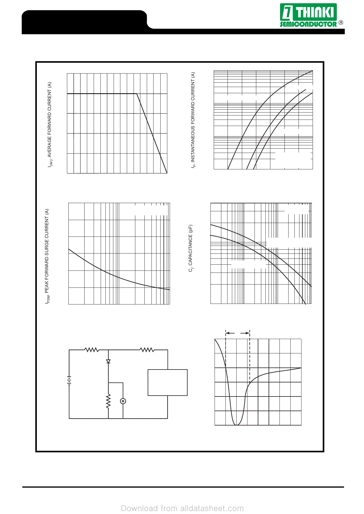
UF1600CT thru UF1608CT
20
16
12
8
4
0
0
225
50
100
150
TC, CASE TEMPERATURE (°C)
Fig. 1 Forward Current Derating Curve
8.3 ms single half-sine-wave
JEDEC method
150
75
100
UF1600CT/UF1601CT/UF1602CT
10
UF1603CT/UF1604CT
UF1606CT/UF1608CT
1.0
Pulse width = 300µs
2% duty cycle
0.1
0
0.6
1.2
1.8
VF, INSTANTANEOUS FORWARD VOLTAGE (V)
Fig. 2 Typical Forward Characteristics
400
Tj = 25°C
f = 1.0MHz
100
UF1600CT/UF1601CT/UF1602CT
UF1603CT/UF1604CT
UF1606CT/UF1608CT
0
1
10
100
NUMBER OF CYCLES AT 60Hz
Fig. 3 Maximum Non-Repetitive Surge Current
50Ω NI (Non-inductive)
10Ω NI
(+)
50V DC
Approx
(-)
Device
Under
Test
1.0Ω
NI
Oscilloscope
(Note 1)
(-)
Pulse
Generator
(Note 2)
(+)
10
0.1
1.0
10
100
VR, REVERSE VOLTAGE (V)
Fig. 4 Typical Junction Capacitance
trr
+0.5A
0A
-0.25A
Notes:
1. Rise Time = 7.0ns max. Input Impedance = 1.0MΩ, 22pF.
2. Rise Time = 10ns max. Input Impedance = 50Ω.
-1.0A
Set time base for 5/10ns/cm
Fig. 5 Reverse Recovery Time Characteristic and Test Circuit
Rev.09T
© 1995 Thinki Semiconductor Co., Ltd.
Page 2/2
http://www.thinkisemi.com.tw/
Share Link: