SM1350ADJM View Datasheet(PDF) - Nippon Precision Circuits
Part Name
Description
Manufacturer
SM1350ADJM Datasheet PDF : 16 Pages
| |||
SM1350ADJM
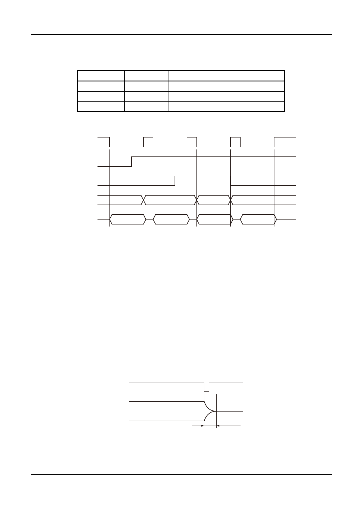
The melody selection in serial mode is controlled by S0 and S1 as shown in the following table. The states of S0 and S1
are read in immediately after startup and the change of S0 and S1 during melody output is invalid.
S1
LOW
HIGH
HIGH
S0
Melody counter
-
Increments when melody output stops
LOW
No increment
HIGH
Increments when melody output starts
Stable 1. S0, S1 resistor and melody counter
STN
S1
S0
Selection Counter
Melody Output
(SP pin)
#N
#N+1
#N+2
#N+2
#N
#N+1
#N+2
#N+2
Figure 10. S0, S1 melody output control timing
STOP pin
One-shot output mode stops when STOP goes from HIGH to LOW. The STOP input is ignored in level hold output
mode and is also ignored in one-shot mode when STN is LOW. Note that even when STOP is LOW, STN has higher
priority.
CT pin
A pulse in sync with selected notes or rests is output on CT. But this function cannot be used with this product.
Fast Damping
When melody output stops, the D/A converter output amplitude dose not fall to zero instantaneously, instead the output
converges to zero within a maximum of 8.2ms to prevent noise being generated. Also, when one-shot melody output
mode is stopped melody output by STOP pin, melody output becomes standby state after the fast damping interval.
When melody out is stopped by ICN input, it instantaneously becomes 0 level.
STOP
Melody Output
(SP pin)
8.2msec
Figure 11. Fast damping timing
SEIKO NPC CORPORATION - 11
Share Link: 