HI-15530PSI(2001) View Datasheet(PDF) - Holt Integrated Circuits
Part Name
Description
Manufacturer
HI-15530PSI Datasheet PDF : 11 Pages
| |||
HI-15530
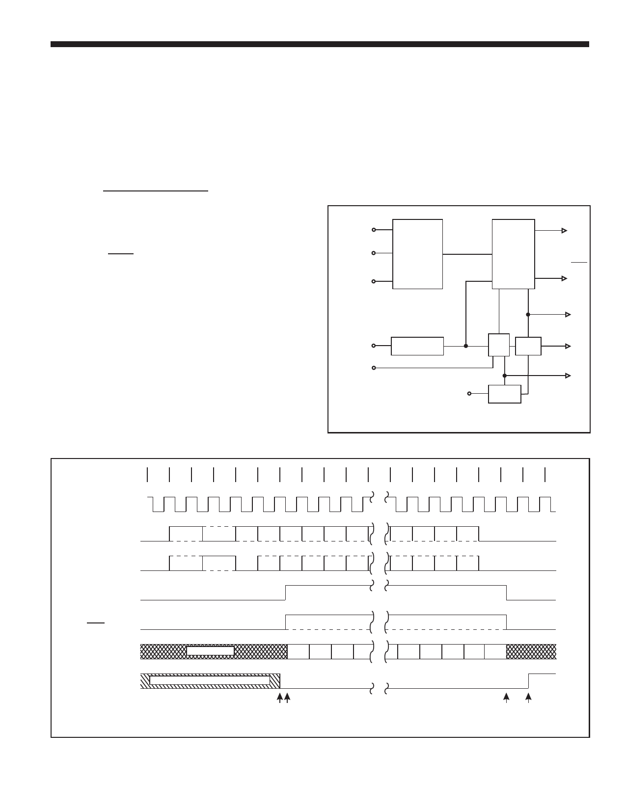
DECODER OPERATION
The Decoder requires a single clock with a frequency of 12
times the desired data rate applied at the DECODER
CLOCK input. The Manchester II coded data can be
presented to the Decoder in one of two ways. The
BIPOLAR ONE and BIPOLAR ZERO inputs will accept
data from a comparator sensed transformer coupled bus as
specified in MIL-STD-1553. The UNIPOLAR DATA input
can only accept non-inverted Manchester II coded data
(e.g. from BIPOLAR ZERO OUT of an Encoder). The
Decoder is free running and continuously monitors its data
input lines for a valid sync character and two valid
Manchester data bits to start an output cycle. When a valid
sync is recognized (1), the type of sync is indicated on
COMMAND/DATA SYNC output. If the sync character was
a command sync, this output will go high (2) and remain
high for sixteen DECODER SHIFT CLOCK periods (3),
otherwise it will remain low. The TAKE DATA output will go
high and remain high (2) - (3) while the Decoder is
transmitting the decoded data through SERIAL DATA OUT.
The decoded data available at SERIAL DATA OUT is in a
NRZ format. The DECODER SHIFT CLOCK is provided so
that the decoded bits can be shifted into an external register
on every low-to-high transition of this clock (2) - (3). After all
sixteen decoded bits have been transmitted (3) the data is
checked for odd parity. A high on VALID WORD output (4)
indicates a successful reception of a word without any
Manchester or parity errors. At this time the Decoder is
looking for a new sync character to start another output
sequence. VALID WORD will go low approximately 20
DECODER SHIFT CLOCK periods after it goes high if not
reset low sooner by a valid sync and two valid Manchester
bits as shown (1). At any time in the above sequence, a
high input on DECODER RESET during a low-to-high
transition of DECODER SHIFT CLOCK will abort
transmission and initialize the Decoder to start looking for a
new sync character.
UNIPOLAR
DATA IN
BIPOLAR
ONE IN
BIPOLAR
ZERO IN
DECODER
CLK
MASTER
RESET
TRANSITION
FINDER
TAKE DATA
CHARACTER
IDENTIFIER
COMMAND/DATA
SYNC
SYNCHRONIZER
DECODER
RESET
SERIAL DATA
OUT
BIT
RATE
CLK
PARITY
CHECK
VALID
WORD
DECODER
SHIFT CLK
BIT
COUNTER
TIMING
DECODER
SHIFT CLK
BIPOLAR
ONE IN
BIPLOAR
ZERO IN
TAKE DATA
COMMAND /
DATA SYNC
SERIAL
DATA OUT
VALID WORD
0
1
2
3
4
5
6
7
8
SYNC SYNC 15 14 13 12 11 10
SYNC SYNC 15 14 13 12 11 10
UNDEFINED
15 14 13 12
May be high from previous reception
(1)(2)
16 17 18 19
2
10
P
2
10
P
4
3
2
10
(3) (4)
HOLT INTEGRATED CIRCUITS
4
Share Link: 