STK672-640C-E View Datasheet(PDF) - ON Semiconductor
Part Name
Description
Manufacturer
STK672-640C-E Datasheet PDF : 27 Pages
| |||
STK672-640C-E
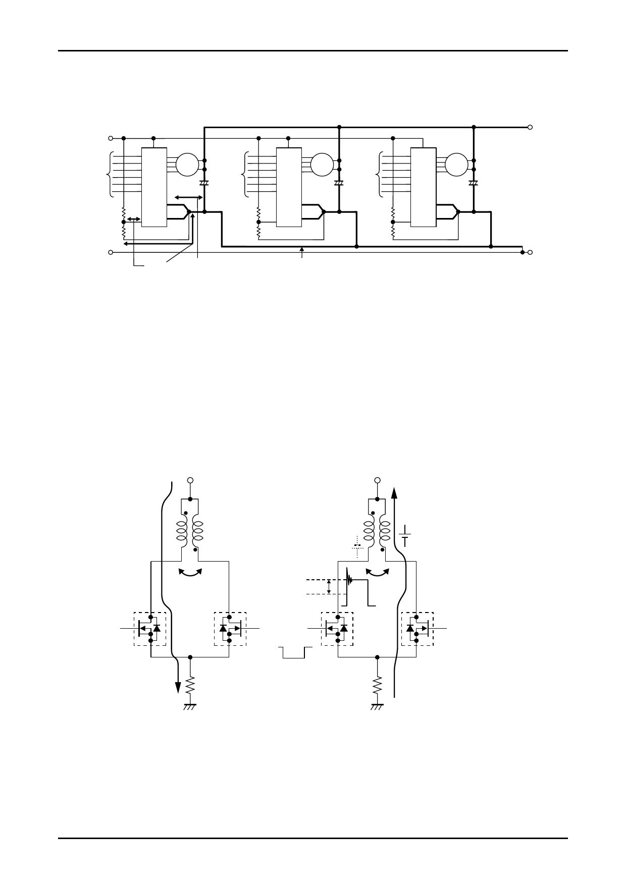
(5) When mounting multiple drivers on a single PC board
When mounting multiple drivers on a single PC board, the GND design should mount a VCC decoupling
capacitor, C1, for each driver to stabilize the GND potential of the other drivers. The key wiring points are as
follows.
24V
5V
Input
Signals
GND
9
Motor
1
IC1
2
6
19 18
Input
Signals
9
Motor
2
IC2
2
6
19 18
Input
Signals
Short
Thick and short
Thick
9
Motor
3
IC3
2
6
19 18
GND
(6) VCC operating limit
When the output (for example F1) of a 2-phase stepping motor driver is turned OFF, the AB phase back
electromotive force eab produced by current flowing to the paired F2 parasitic diode is induced in the F1 side,
causing the output voltage VFB to become twice or more the VCC voltage. This is expressed by the following
formula.
VFB = VCC + eab
= VCC + VCC + IOH × RM + Vdf (1.5 V)
VCC: Motor supply voltage, IOH: Motor current set by Vref
Vdf: Voltage drop due to F2 parasitic diode and current detection resistor R1, RM: Motor winding resistance
value
Using the above formula, make sure that VFB is always less than the MOSFET withstand voltage of 100V. This
is because there is a possibility that operating limit of VCC falls below the allowable operating range of 46V, due
to the RM and IOH specifications.
VCC
VCC
A phase
The pass of
drain current
F1
ON
AB phase
A phase
Eab is induced by
inducing M.
VFB
M
eab
F2
VCC
OFF F1
OFF
AB phase
eab
The pass of
negative current
M
F2
OFF
R1
GND
R1
GND
The oscillating voltage in excess of VFB is caused by LCRM (inductance, capacitor, resistor, mutual inductance)
oscillation that includes micro capacitors C, not present in the circuit. Since M is affected by the motor
characteristics, there is some difference in oscillating voltage according to the motor specifications. In addition,
constant voltage drive without constant current drive enables motor rotation at VCC ≥ 0V.
No. A2116-26/27
Share Link: 